Spinning oil feeder

A technology of oil feeder and oil tank, which is applied in the direction of engine components, engine lubrication, mechanical equipment, etc., can solve the problems of non-universal use, different final requirements of raw materials, lack of oil installation and fixing devices, etc., and achieve simple structure and convenient operation Effect

Inactive Publication Date: 2016-08-10
XINCHANG COUNTY XINLIANXING TEXTILE CO LTD
View PDF0 Cites 2 Cited by
  • Summary
  • Abstract
  • Description
  • Claims
  • Application Information

AI Technical Summary

Problems solved by technology

Even if the same type of equipment, the structure of the machine is similar, but due to the different properties of the raw materials and the final requirements for the fabric, it is generally not common
However, the existing special oil supply for textile equipment lacks devices that help the output and supply of oil and the installation and fixing of auxiliary parts. The lubricating supply time of the fluid and the device that helps to realize the suspension function of the pipeline and the porous box cannot meet the needs of the actual situation

Method used


Image

  • Spinning oil feeder

Examples


Embodiment Construction

[0010] Below in conjunction with accompanying drawing, the present invention will be further described:

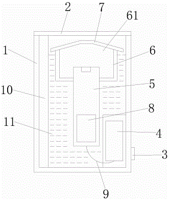
[0011] A textile oil supply device, comprising an oil tank 1, the material of the oil tank 1 is stainless steel, the upper end surface of the oil tank 1 is a sealing plate 2, the oil tank 1 is provided with a card seat 3, and the oil tank 1 is provided with Out of the oil tank, the sealing plate 2, the card seat 3, the output chamber 4 and the thin tube 9 are helpful for the output and supply of oil and the installation and fixing of auxiliary parts. The oil outlet tank is provided with an output chamber 4.

[0012] The middle part of the inner cavity of the fuel tank 1 is provided with a vertical pipeline 5, and the front part of the pipeline 5 is equipped with a porous box 6, and the pipeline 5 fixedly connected with the porous box 6 is separated from the fuel tank 1, and the pipeline 5, the porous box 6, the sponge The block 61, the oil-soaked plate 7 and the floating b...


PUM


Abstract

The invention relates to a textile oil supply device. It is characterized in that it includes a fuel tank, the upper end surface of the fuel tank is a sealing plate, a deck is provided on the fuel tank, a fuel outlet tank is provided in the fuel tank, an output cavity is provided in the fuel outlet tank, and the inner cavity of the fuel tank There is a vertical pipeline in the middle, a porous box is installed in the front of the pipeline, a sponge block is installed in the porous box, an oil-soaked plate is arranged above it, and a floating block is installed at the lower end of the porous box. The output chambers are connected to each other, and oil is arranged in the inner cavity of the oil tank. Compared with the existing technology, the beneficial effects of the present invention are: the present invention facilitates the output and supply of oil and the installation and fixation of auxiliary parts by setting the sealing plate, the clamp, the output chamber and the thin tube; The box, sponge block, oil-soaked plate and floating block not only help to store the oil and prolong the lubrication supply time of the oil, but also help to realize the suspension function of the pipeline and the porous box, and are simple in structure, easy to operate, economical and practical.

Description

technical field [0001] The invention relates to a textile oil supply device. Background technique [0002] Textile machinery is all kinds of mechanical equipment needed to process natural fibers or chemical fibers into textiles. Although the machinery for producing chemical fibers includes a variety of chemical machinery, it is now considered an extension of textile machinery and belongs to textile machinery in a broad sense. Different fibers such as cotton, linen, silk, and wool require different processes, some of which are completely different, so the machines required are also varied and varied. Textile machinery is usually classified according to the production process, including: spinning equipment, weaving equipment, printing and dyeing equipment, finishing equipment, chemical fiber spinning equipment, reeling equipment and non-woven fabric equipment. Spinning equipment is divided into two categories: processing short fibers and processing long fibers. Cotton and c...

Claims


Application Information

Patent Timeline
Patent Type & Authority Applications(China)
IPC IPC(8): F16N7/00
CPCF16N7/00
Inventor 潘文彬
Owner XINCHANG COUNTY XINLIANXING TEXTILE CO LTD
Why Eureka
Try Eureka