a heat exchanger

A technology for heat exchangers and the other side, applied in heat exchange equipment, heat exchanger types, indirect heat exchangers, etc., can solve problems such as high production costs, complex heat exchanger structures, and low heat exchange efficiency , to achieve the effect of low thermal resistance, wide application range and high heat transfer efficiency

Active Publication Date: 2017-12-01
佛山市威沃热能科技有限公司
View PDF7 Cites 1 Cited by
  • Summary
  • Abstract
  • Description
  • Claims
  • Application Information

AI Technical Summary

Problems solved by technology

[0002] The current finned heat exchanger is composed of fins and pipes. The fins and pipes are produced separately, and then the fins are fixed on the pipes. On the one hand, due to the different materials and contact between the fins and the pipes There is a gap due to poor performance, the thermal resistance between the two is large, and the heat transfer efficiency is relatively low. On the other hand, this type of heat exchanger has a complex structure and difficult production, resulting in high production costs

Method used


Image

  • a heat exchanger
  • a heat exchanger
  • a heat exchanger

Examples


Embodiment Construction

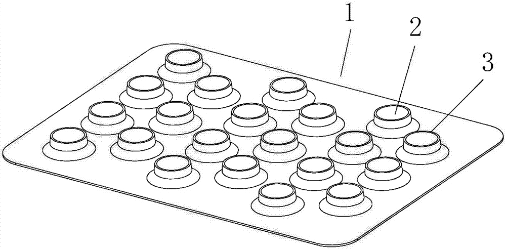
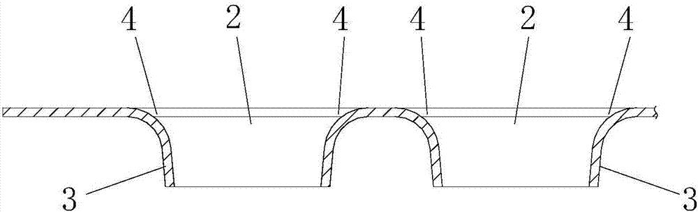
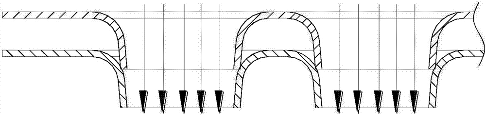
[0023] refer to Figure 1 to Figure 7 , a heat exchanger formed by stacking a number of laminations 1, said lamination 1 is provided with at least one flanging hole 2, the flanging hole 2 can be a round hole, or a hole of other shapes, such as oval Shaped or other shapes of special-shaped holes, etc. One side of the flanged hole 2 extends outwards higher than the surface of the lamination 1 to form an insertion portion 3 , and the other side forms a receiving portion 4 , the transition between the receiving portion 4 and the lamination 1 The parts are arc-shaped chamfers. After several laminations 1 are laminated, the insertion part 3 of the next lamination 1 is sealed and connected with the receiving part 4 of the previous lamination 1 to form a pipeline space. The pipeline space is equivalent to that of the prior art. The internal channel of the middle pipeline can pass through liquid or gas, and the pipeline space is connected by a joint pipe to form a Figure 4 The gas-t...


PUM


Abstract

The invention discloses a heat exchanger which is formed by stacking laminations. Each lamination is provided with at least one flanging hole. One side of each flanging hole extends outwards and is higher than the surface of the corresponding lamination to form an insertion connection part, and the other side of each flanging hole forms a connected part. After the laminations are stacked, the insertion connection parts of the lower laminations and the connected parts of the upper laminations are connected in a sealing mode to form pipeline space. The pipeline spaces are equivalent to inner channels of pipelines in the prior art, pipelines of a finned heat exchanger in the prior art are omitted, the structure of the heat exchanger is simplified, and production cost of the product can be effectively reduced. The pipeline spaces are composed of the insertion connection parts and the connected parts on the laminations, the material of the pipeline spaces and the material of the laminations are the same, and no media exist, so that thermal resistance is low, heat exchange efficiency can be effectively improved, and the heat exchanger has the advantages of being small in thermal resistance, high in heat exchange efficiency, convenient to manufacture, wide in application range and the like.

Description

technical field [0001] The invention relates to an energy exchange device, in particular to a heat exchanger. Background technique [0002] The current finned heat exchanger is composed of fins and pipes. The fins and pipes are produced separately, and then the fins are fixed on the pipes. On the one hand, due to the different materials and contact between the fins and the pipes There are gaps due to defects, the thermal resistance between the two is relatively large, and the heat exchange efficiency is relatively low. On the other hand, this type of heat exchanger has a complex structure and difficult production, resulting in high production costs. Contents of the invention [0003] In order to overcome the deficiencies of the prior art, the invention provides a heat exchanger with small thermal resistance, high heat exchange efficiency and convenient manufacture. [0004] The technical solution adopted by the present invention to solve its technical problems is: [000...

Claims


Application Information

Patent Timeline
Patent Type & Authority Patents(China)
IPC IPC(8): F28D1/047F28F1/30
CPCF28D1/0475F28F1/30
Inventor 高月云
Owner 佛山市威沃热能科技有限公司
Why Eureka
Try Eureka