
Depth dial gauge

A technology of depth indication and indication, applied in the direction of mechanical depth measurement, etc., can solve the problems of low production efficiency, tedious operation process, and the inability to measure the dial indicator.

Inactive Publication Date: 2016-08-10
镇江奥立特机械制造有限公司
View PDF5 Cites 0 Cited by
  • Summary
  • Abstract
  • Description
  • Claims
  • Application Information

AI Technical Summary

Problems solved by technology

[0002] The measurement accuracy of the percentage indicator can reach 0.01mm, and it is widely used to measure the flatness of objects, and to measure the depth of some grooves or grooves that are wide and easy for the dial gauge probe to penetrate into. However, for For some grooves or grooves with narrow width or special specifications, the dial indicator cannot be measured
[0003] like Figure 4 As shown, the sleeve is generally used for fixing and installing the collet on the machine tool. According to the needs of customers, the manufacturer generally produces one or several specific sleeves in batches. There is an annular groove 9 for installation inside the sleeve. The distance from the cutting surface of the groove 9 to the outermost cutting surface of the sleeve is strictly regulated, and the error generally cannot exceed 0.05mm. Because the manufacturers generally produce in large quantities in a unified manner, and the general percentage indicator or vernier caliper is used to measure the depth. A relatively cumbersome operation process is required, which is not conducive to the batch inspection of products, resulting in low production efficiency during actual measurement, and cannot guarantee the pass rate of products

Method used


Image

  • Depth dial gauge
  • Depth dial gauge
  • Depth dial gauge

Examples


Embodiment Construction

[0020] The following will clearly and completely describe the technical solutions in the embodiments of the present invention with reference to the accompanying drawings in the embodiments of the present invention. Obviously, the described embodiments are only some, not all, embodiments of the present invention. Based on the embodiments of the present invention, all other embodiments obtained by persons of ordinary skill in the art without creative efforts fall within the protection scope of the present invention.

[0021] The invention is used to calibrate and measure the distance from the cut surface of the ring groove to the outermost cut surface of the sleeve of a mechanical sleeve with an annular groove. And the advantages of pass rate.

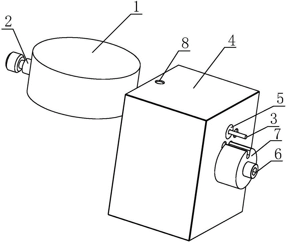
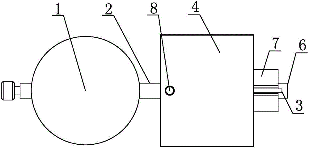
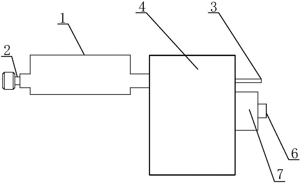
[0022] Such as figure 1 As shown, a depth indicator table includes an indicating dial 1 and a measuring rod 2 passing through the indicating dial 1, and one end of the measuring rod 2 extending out of the indicating dial 1 is provided ...


PUM


Abstract

The utility model discloses a depth dial gauge. The depth dial gauge comprises an indication dial plate, a measuring rod and a mounting block; one end of the measuring rod, which extends out of the indicating dial plate, is provided with a telescopic measuring head; a through hole extending from one side to the other side of the mounting block is formed in the mounting block; the measuring rod penetrates the through hole and extends out from the measuring head; one side surface, from which the measuring head extends out, of the mounting block is provided with a positioning column; the positioning column is sheathed with a calibration ring; the axis of the calibration ring is parallel to the measuring head; and the length of the axis of the calibration ring is greater than the length of the measuring head extending out from the through hole. The depth dial gauge disclosed by the invention is used for calibrating and measuring the distance between the section of an annular groove of a mechanical sleeve with the annular groove and the outermost peripheral section of the sleeve, and has the advantages of simple structure, convenient operation, capability of quickly determining and finding out unqualified products, and capability of greatly improving the production efficiency and qualification rate of products.

Description

technical field [0001] The invention relates to an improvement of a percentage indicator, in particular to a depth indicator for calibrating and measuring the depth of a groove or groove. Background technique [0002] The measurement accuracy of the percentage indicator can reach 0.01mm, and it is widely used to measure the flatness of objects, and to measure the depth of some grooves or grooves that are wide and easy for the dial gauge probe to penetrate into. However, for For some grooves or grooves with narrow width or special specifications, the dial indicator cannot be measured. [0003] Such as Figure 4 As shown, the sleeve is generally used for fixing and installing the collet on the machine tool. According to the needs of customers, the manufacturer generally produces one or several specific sleeves in batches. There is an annular groove 9 for installation inside the sleeve. The distance from the cutting surface of the groove 9 to the outermost cutting surface of t...

Claims


Application Information

Patent Timeline
Patent Type & Authority Applications(China)
IPC IPC(8): G01B5/18
CPCG01B5/18
Inventor 祝龙云
Owner 镇江奥立特机械制造有限公司
Learn More