Self-propelled ship model test device applicable to arbitrary wave direction and application method for the same

A technology for testing and sailing ships, which is applied in the field of self-propelled ship model test and testing devices, can solve the problems of ship model yaw, affect the accuracy of test data, violate the self-propelled test method, etc., and achieve the effect of simplifying the test method and high precision

Inactive Publication Date: 2016-08-10
HARBIN INST OF TECH AT WEIHAI
View PDF6 Cites 32 Cited by
  • Summary
  • Abstract
  • Description
  • Claims
  • Application Information

AI Technical Summary

Problems solved by technology

[0003] Most of the self-propulsion is head sea, but the direction of the waves encountered in the actual sea conditions is often random. At present, there are few experimental data of oblique waves in the literature, which cannot provide experimental basis f...

Method used


Image

  • Self-propelled ship model test device applicable to arbitrary wave direction and application method for the same
  • Self-propelled ship model test device applicable to arbitrary wave direction and application method for the same
  • Self-propelled ship model test device applicable to arbitrary wave direction and application method for the same

Examples


Embodiment 1

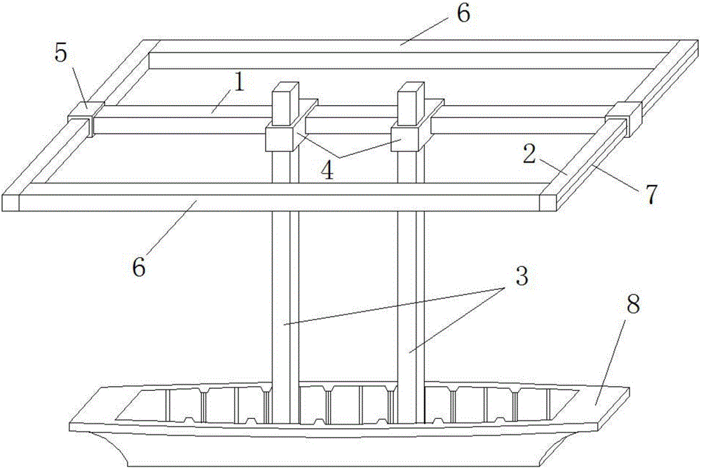
[0029] The self-propelled ship model test device applicable to any wave direction includes track I1, track II2, track III3, universal base 23 and elastic device 7, the universal base 23 is arranged at the bottom of track III3, and track III3 is arranged in parallel with There are two rails, and there are two rails Ⅱ2 in parallel. The rails Ⅰ1 and Ⅱ2 are vertical and in the same plane. The rail Ⅲ3 is perpendicular to the plane where the rails Ⅰ1 and Ⅱ2 are located. Located on the same side of the track I1, the two ends of the track I1 are connected to the two tracks II2 through a sliding device, and the two sides of the end of the track I1 are respectively equipped with elastic devices 7, one end of the elastic device 7 is connected to the end of the track I1, and the other end is connected to the end of the track I1. Track II2 connection.

[0030] Such as figure 1 As shown, the sliding device is a slider, and there is a slider II5 on the track II2, and the two ends of the tra...

Embodiment 2

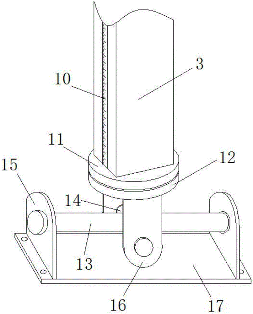
[0044] In this embodiment, the difference from Embodiment 1 is that the relative sliding between the rails in Embodiment 1 is through sliders, that is, through sliding friction. In this embodiment, the sliding between rails is through rollers, that is, by means of rolling friction. When the track width is large and the contact surface between the slider and the track increases, the connection method of the slider will affect the test accuracy, and changing the sliding friction to rolling friction can solve the above problems well.

[0045] Such as Figure 5 to Figure 7 As shown, it is a preferred embodiment, the track I1 is provided with a sliding device I, the sliding device I includes a roller bracket II20 and rollers, the track III3 is provided with a sliding device III, and the sliding device III includes a roller bracket III and rollers, The roller bracket II20 is fixedly connected with the roller bracket III; the track II2 is provided with a sliding device II, the slidi...


PUM


Abstract

The invention relates to a self-propelled ship model test device suitable for any wave direction and a use method thereof, belonging to the technical field of wave load testing of ships and marine engineering. The invention solves the technical problem that accurate test data cannot be obtained in the self-propelled ship model test in any wave direction at present. The present invention includes track I, track II, track III, a universal base and an elastic device. The universal base is arranged at the bottom end of track III, two tracks of track III are arranged in parallel, two tracks of track II are arranged in parallel, track I and track II Vertical and in the same plane, track III is perpendicular to the plane where track I and track II are located, track III is connected to track I through a sliding device, both ends of track I are connected to two tracks II through sliding devices, and the two ends of track I are connected. The sides are respectively provided with elastic devices, one end of the elastic device is connected with the end of the track I, and the other end is connected with the track II. The invention is used for self-propelled ship model test.

Description

technical field [0001] The invention relates to a self-propelled ship model test device applicable to any wave direction and a use method thereof, belonging to the technical field of ship and ocean engineering wave load testing. Background technique [0002] According to different propulsion methods, ship model tests can be roughly divided into two types: towing and self-propelled. In the towing test, the speed of the ship model is guaranteed by the trailer in the towing pool. The trailer is equipped with a vehicle speed control system to ensure that the trailer runs at the predetermined speed, so the sailing state of the hull in the waves cannot be reflected, which will affect the test results. come error. At present, studies have pointed out that the towing test method will increase the high-frequency components in the load response, while the self-propulsion test can truly reflect the load characteristics in the actual sailing state and predict the propulsion performance...

Claims


Application Information

Patent Timeline
IPC IPC(8): G01M10/00
CPCG01M10/00
Inventor 陈占阳
Owner HARBIN INST OF TECH AT WEIHAI
Why Eureka
Try Eureka