Radar blind area analysis method and device

A radar blind area and analysis method technology, applied in the field of detection, can solve the problems of cumbersome steps, time-consuming, large amount of calculation, etc., and achieve the effect of reducing the calculation steps

Active Publication Date: 2016-08-10
CHENGDU ZHONGKE HEXUN TECH CO LTD
View PDF5 Cites 19 Cited by
  • Summary
  • Abstract
  • Description
  • Claims
  • Application Information

AI Technical Summary

Problems solved by technology

However, the steps of the above calculation method are cumbersome, computationally intensive, and time-consuming.

Method used

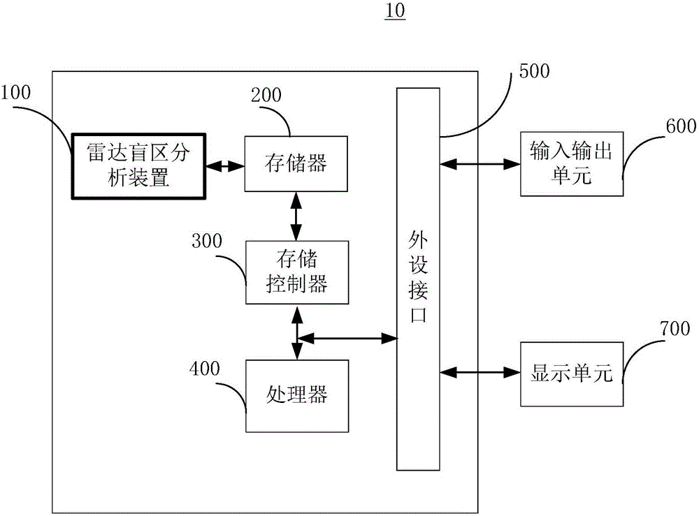

Image

  • Radar blind area analysis method and device
  • Radar blind area analysis method and device
  • Radar blind area analysis method and device

Examples


Embodiment Construction

[0048] In order to make the purpose, technical solutions and advantages of the embodiments of the present invention clearer, the technical solutions in the embodiments of the present invention will be clearly and completely described below in conjunction with the drawings in the embodiments of the present invention. Obviously, the described embodiments It is a part of embodiments of the present invention, but not all embodiments. Based on the embodiments of the present invention, all other embodiments obtained by persons of ordinary skill in the art without making creative efforts belong to the protection scope of the present invention.

[0049] It should be noted that like numerals and letters denote similar items in the following figures, therefore, once an item is defined in one figure, it does not require further definition and explanation in subsequent figures. Meanwhile, in the description of the present invention, the terms "first", "second", etc. are only used to disti...


PUM


Abstract

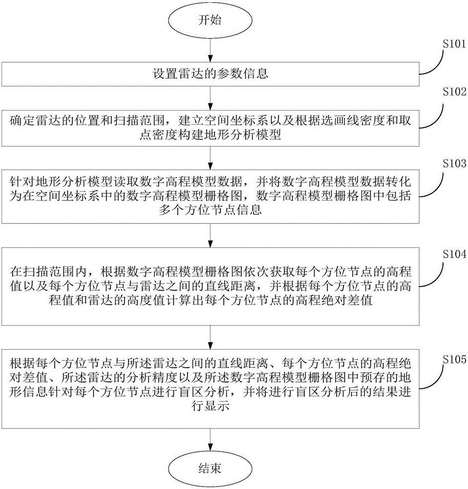
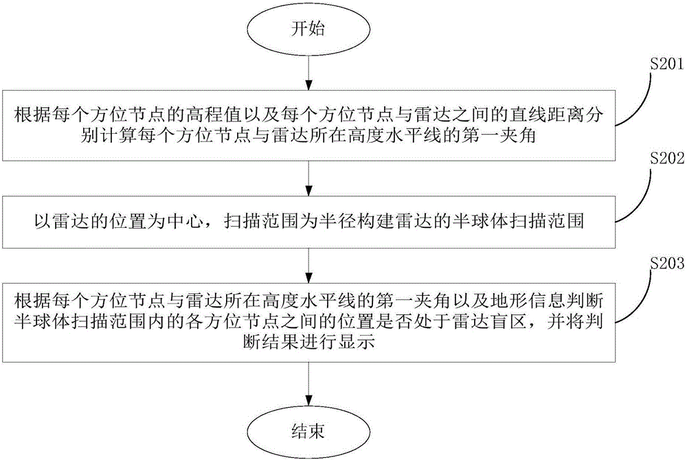
The embodiment of the invention provides a radar blind area analysis method and device, and belongs to the technical field of detection. The radar blind area analysis method comprises the steps that the location and the scanning range of radar are determined, and a terrain analysis model is constructed according to preset line selecting and drawing density and point taking density; digital elevation model data are converted into digital elevation model grid maps; the elevation value of each azimuth node and the straight-line distance between each azimuth node and the radar are acquired according to the digital elevation model grid maps, and the elevation absolute difference value of each azimuth node is calculated; and blind area analysis is performed according to the straight-line distance between each azimuth node and the radar, the elevation absolute difference value of each azimuth node, the analytical precision of the radar and the pre-stored terrain information of the digital elevation model grid maps, and the result of blind area analysis is displayed. The calculation steps, the calculation amount and calculation time consumption of calculation of radar blind areas can be effectively reduced.

Description

technical field [0001] The present invention relates to the technical field of detection, in particular to a radar blind spot analysis method and device. Background technique [0002] Radar is an electronic device that uses electromagnetic waves to detect target points. It is mainly used for radio detection and ranging. It uses radio methods to find target points and determine the spatial position of target points. The radar emits electromagnetic waves to irradiate the target point and receives its echo, and can obtain information such as the distance from the target point to the electromagnetic wave emission point, the distance change rate (radial velocity), azimuth, and altitude. Radar has been widely used in all walks of life, and its detection accuracy is getting higher and higher. However, due to factors such as the curvature of the earth, ground clutter interference, and terrain shadowing, radar detection technology has scanning blind spots. Among them, during the pr...

Claims


Application Information

Patent Timeline
Patent Type & Authority Applications(China)
IPC IPC(8): G01S7/41
CPCG01S7/41
Inventor 朱金华李飞
Owner CHENGDU ZHONGKE HEXUN TECH CO LTD
Why Eureka
Try Eureka