Projection device

A technology of a projection device and a projection lens, which is applied in the field of projectors, can solve the problems of poor air ducts, affecting the lifespan, and reducing the heat dissipation efficiency of the projector, and achieves the effect of improving the heat dissipation efficiency.

Active Publication Date: 2016-08-10
QISDA OPTRONICS (SUZHOU) CO LTD +1
View PDF12 Cites 7 Cited by
  • Summary
  • Abstract
  • Description
  • Claims
  • Application Information

AI Technical Summary

Problems solved by technology

At the same time, in order to facilitate the use of users, the existing projector also adopts a lamp holder type power supply structure, and directly uses the lamp holder to connect the projector to an external power source, but when the lamp holder is used to cooperate with the projector shell, it is very easy to block Wind flow, resulting in poor air ducts, reducing air flow, resulting in a reduction in the cooling performance of the projector, and even affecting the life of the projector

Method used


Image

  • Projection device
  • Projection device
  • Projection device

Examples


Embodiment Construction

[0021] In order to have a further understanding of the purpose, structure, features, and functions of the present invention, the following detailed descriptions are provided in conjunction with the embodiments.

[0022] Certain terms are used in the description and claims to refer to particular elements. Those of ordinary skill in the art will appreciate that manufacturers may refer to the same element by different terms. The specification and claims do not use the difference in name as a way to distinguish components, but use the difference in function of components as a criterion for distinguishing. "Include" mentioned throughout the specification and claims is an open term, so it should be interpreted as "including but not limited to".

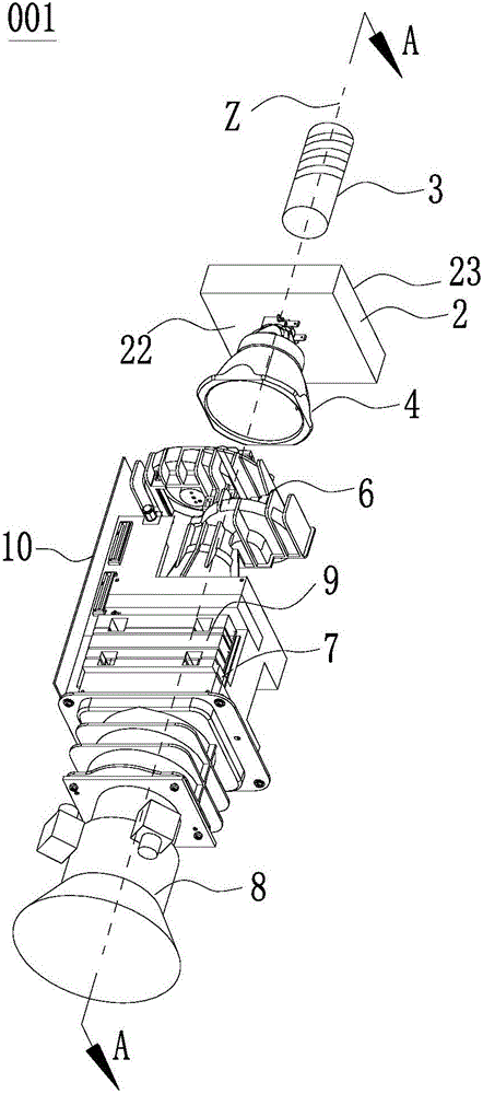
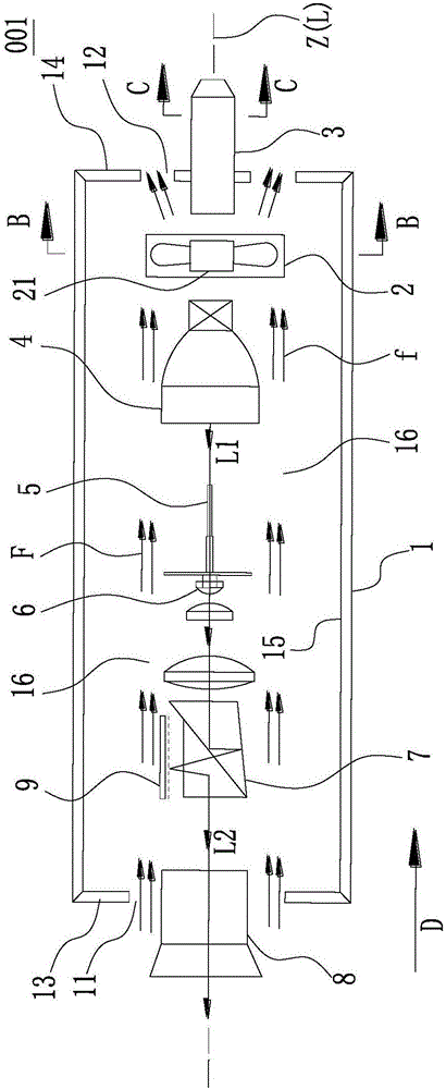
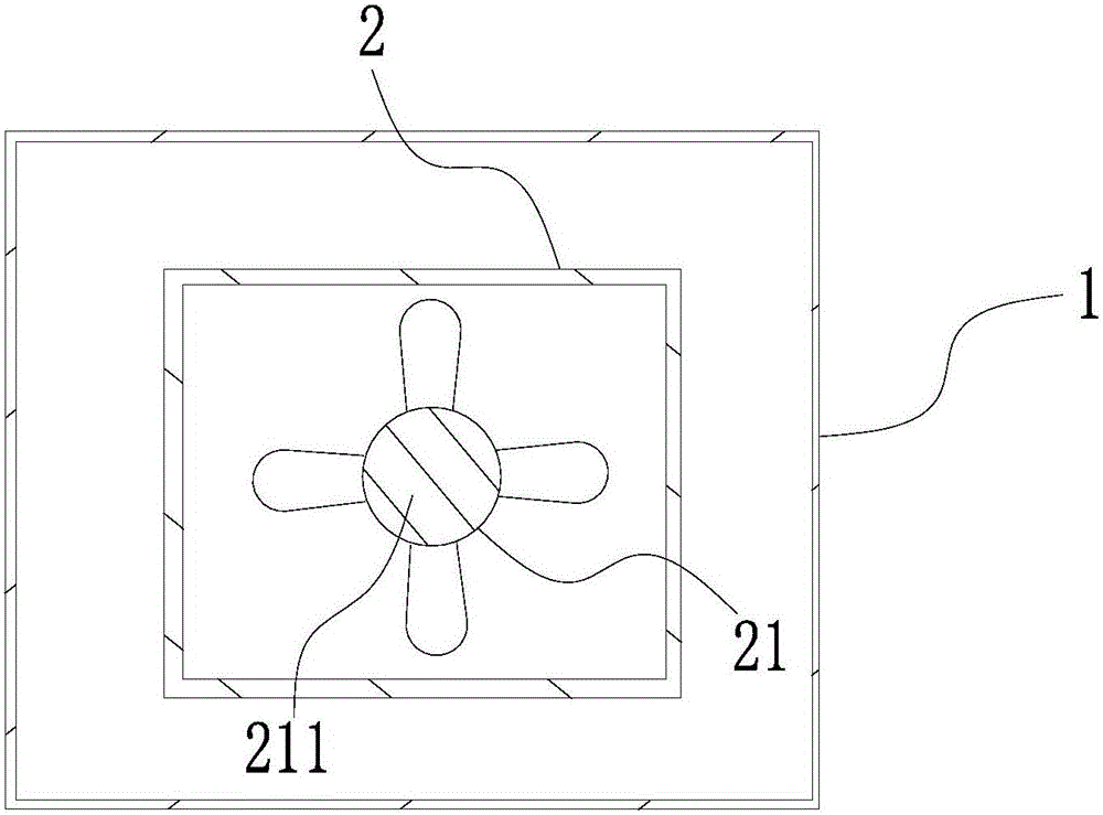
[0023] refer to Figure 1 to Figure 4 As shown, a schematic structural diagram of the first embodiment of the projection device of the present invention is disclosed. in, figure 1 It is a three-dimensional schematic diagram of the inter...


PUM


Abstract

Provided in the invention is a projection device comprising a housing, an optical machine assembly, a fan, and a lamp holder. The housing has a first air port and a second air port, wherein the two ports are opposite to each other. The optical machine assembly is arranged in the housing. The fan arranged in the housing is used for generating an air flow and has an axis. The lamp holder facing the axis directly is connected with an external power supply and has a first cross section; and the area of the first cross section matches the area of the cross section of the axis. The air flow can flow along a linear air flue between the first air port and the second air port to cool the optical machine assembly. Therefore, the air flue structure can be optimized and thus the maximum air flow can be obtained.

Description

technical field [0001] The invention relates to the field of projectors, in particular to a linearly arranged projector cooling structure. Background technique [0002] With the continuous development of projector technology, users have put forward higher requirements on the volume, weight, heat dissipation, noise and other aspects of the projector. Existing projectors include multiple heat sources such as light sources, lenses, and optical-mechanical components. In order to dissipate heat from each heat source, multiple cooling fans are usually installed to cooperate with the complex air duct structure. The increase in the number of fans in this design leads to a larger volume , weight, noise and other indicators are not satisfactory; and the complex air duct structure increases the air flow loss and greatly reduces the heat dissipation efficiency. [0003] In order to avoid the above problems, people began to design the projector into a linear structure and use a single f...

Claims


Application Information

Patent Timeline
Patent Type & Authority Applications(China)
IPC IPC(8): G03B21/16
CPCG03B21/16
Inventor 萧启宏吴宗训
Owner QISDA OPTRONICS (SUZHOU) CO LTD
Why Eureka
Try Eureka