Production method of antenna assembly and antenna assembly

A technology of an antenna assembly and a manufacturing method, applied in the field of antennas, can solve the problems of flux overflow, poor detection, deformation, etc.

Active Publication Date: 2016-08-10
GOERTEK INC
View PDF7 Cites 2 Cited by
  • Summary
  • Abstract
  • Description
  • Claims
  • Application Information

AI Technical Summary

Problems solved by technology

[0003] like figure 1 As shown, the assembly method of the antenna assembly 100 of the existing product is that the shrapnel 130 is directly welded on the plastic antenna 110 through the solder paste layer 120. There are many problems in this assembly structure. After the shrapnel 130 is welded to the plastic antenna 110 through the solder paste layer 120 , will cause solder paste overflow, flux overflow, etc., which will affect the appearance of the product; the solder paste layer 120 is located at the bottom of the spring 130 and covered by the spring 1

Method used


Image

  • Production method of antenna assembly and antenna assembly
  • Production method of antenna assembly and antenna assembly
  • Production method of antenna assembly and antenna assembly

Examples


Embodiment Construction

[0030] In order to make the object, technical solution and advantages of the present invention clearer, the implementation manner of the present invention will be further described in detail below in conjunction with the accompanying drawings.

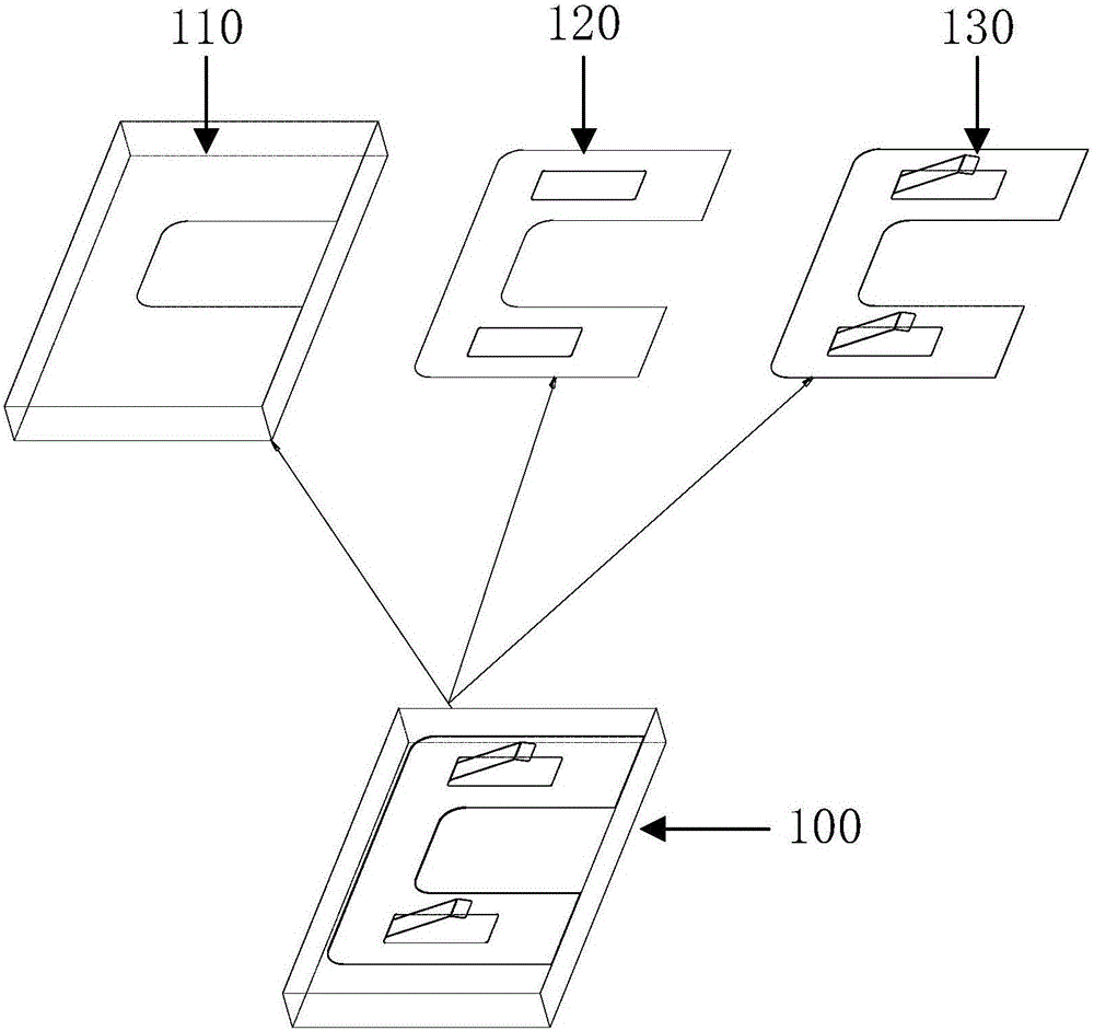
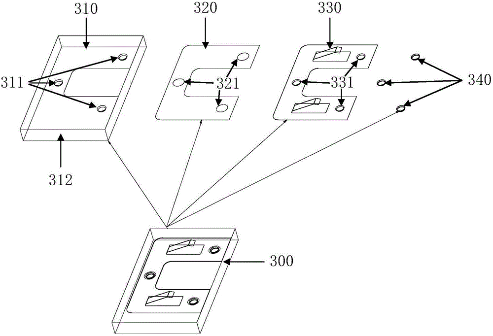
[0031] figure 2 A flow chart of a manufacturing method of an antenna assembly provided by an embodiment of the present invention; image 3 An exploded diagram of an antenna assembly provided for an embodiment of the present invention; Figure 4 A top view of an antenna assembly provided by an embodiment of the present invention; Figure 5 for Figure 4 A-A sectional view of the antenna assembly shown; Figure 6 for Figure 5 An enlarged view of the circular area of ​​the A-A sectional view of the antenna assembly shown.

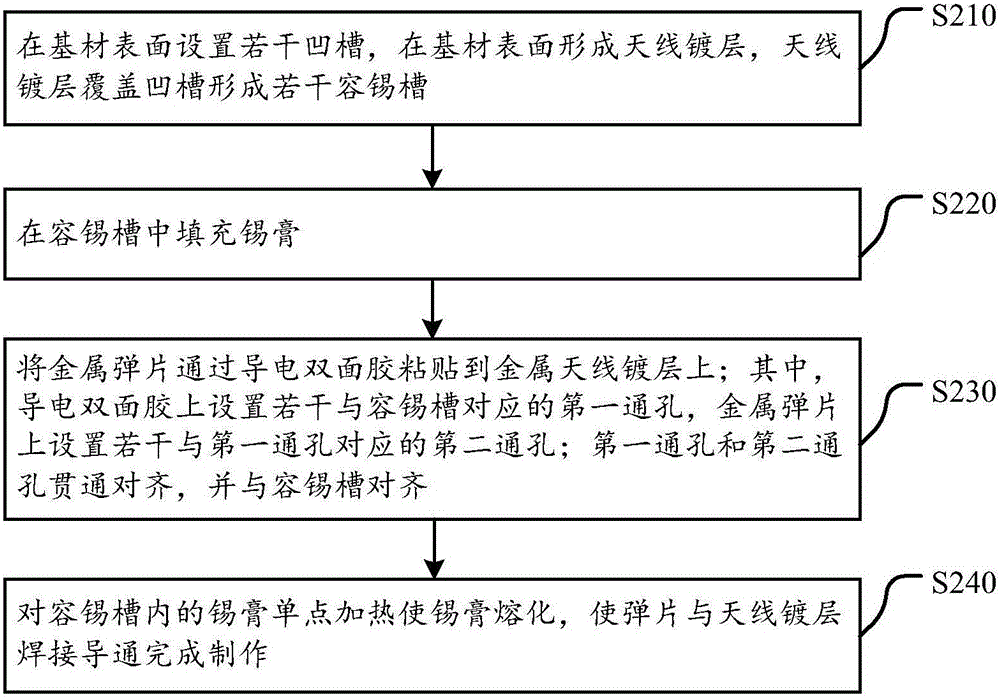
[0032] The flow chart of a manufacturing method of an antenna assembly disclosed by the present invention is as follows: figure 2 As shown, the structure of the antenna assembly made according to this method i...


PUM


Abstract

The invention discloses a production method of an antenna assembly and an antenna assembly. The production method is characterized in that a plurality of grooves are disposed in a surface of a base material, and the surface of the base material is provided with a metal antenna coating, which is used to cover the grooves to form a plurality of tin accommodation grooves; the tin pastes can be disposed in the tin accommodation grooves in a filled manner; a metal elastic sheet is disposed on the metal antenna coating in an adhesive manner by a conductive double-sided adhesive tape; the conductive double-sided adhesive tape is provided with a plurality of first through holes corresponding to the tin accommodation grooves, and the metal elastic sheet is provided with a plurality of second through holes corresponding to the first through holes; the first through holes and the second through holes are aligned with each other in a penetrating manner, and are aligned with the tin accommodation grooves; the single-point heating of the tin pastes in the tin accommodation grooves can be carried out to melt the tin pastes, and then the metal elastic sheet can be conducted with the metal antenna coating to complete the production. The production method is advantageous in that the antenna assembly can be produced in a way of combining the adhesive connection using the conductive double-sided adhesive tape with the single-point welding, and therefore the overflowing of the soldering paste and the flux can be prevented, the consistency of the elastic sheet assembly height can be improved, the good conduction between the antenna coating and the elastic sheet can be realized, and the quality of the tin pastes can be observed directly.

Description

technical field [0001] The invention relates to the technical field of antennas, in particular to a manufacturing method of an antenna component and an antenna component. Background technique [0002] At present, with the continuous development of electronic products and the advent of the SMART era, wireless networks are used more and more frequently, and the antenna requirements for consumer electronic products such as mobile phones, laptops, PADs, stereos, smart watches, and routers are getting higher and higher. [0003] Such as figure 1 As shown, the assembly method of the antenna assembly 100 of the existing product is that the shrapnel 130 is directly welded on the plastic antenna 110 through the solder paste layer 120. There are many problems in this assembly structure. After the shrapnel 130 is welded to the plastic antenna 110 through the solder paste layer 120 , will cause solder paste overflow, flux overflow, etc., which will affect the appearance of the product;...

Claims


Application Information

Patent Timeline
IPC IPC(8): H01Q1/36H01Q1/38
CPCH01Q1/36H01Q1/38
Inventor 刘建春许洋洋林增帅
Owner GOERTEK INC
Why Eureka
Try Eureka