Signal amplification circuit, metallic detector formed by signal amplification circuit and signal amplification method

A signal amplification circuit and amplifier technology, which is applied in the field of metal detectors, can solve the problems of great difficulty in detection, limited measurement range, and the limit value of the input signal amplification factor can only be 10 times, so as to achieve the reduction of false alarms and false alarms. Effect of Signal Detection Capability Improvement

Pending Publication Date: 2016-08-10
DONGGUAN HUADUN ELECTRONICS TECH CO LTD
View PDF5 Cites 3 Cited by
  • Summary
  • Abstract
  • Description
  • Claims
  • Application Information

AI Technical Summary

Problems solved by technology

[0004] However, on the other hand, it is limited by the measurement range of analog-to-digital conversion sampling. For example, when the range of the analog-to-digital conversion chip is 5V, the peak-to-peak value of the maximum output signal of the operator can only be 5V. The peak value is 0.5V, and the limit value of the input signal amplification factor can only be 10 times
In this way, when the input signal variation of the measurement circuit is 1mV, the signal that can be measured is 10mV, and the magnification of the signal variation is 10 times. This weak electromotive force variation is very difficult to detect, so a new type of signal is needed The amplification circuit, the new metal detector based on the circuit and the new signal amplification method based on the circuit can improve the detection ability of the signal variation and avoid false alarms. Such technology is currently not in the existing found in technology

Method used


Image

  • Signal amplification circuit, metallic detector formed by signal amplification circuit and signal amplification method
  • Signal amplification circuit, metallic detector formed by signal amplification circuit and signal amplification method
  • Signal amplification circuit, metallic detector formed by signal amplification circuit and signal amplification method

Examples


Embodiment Construction

[0090] The present invention will be further described below in conjunction with the accompanying drawings and embodiments, but the scope of protection of the present invention is not limited to the scope described in the embodiments.

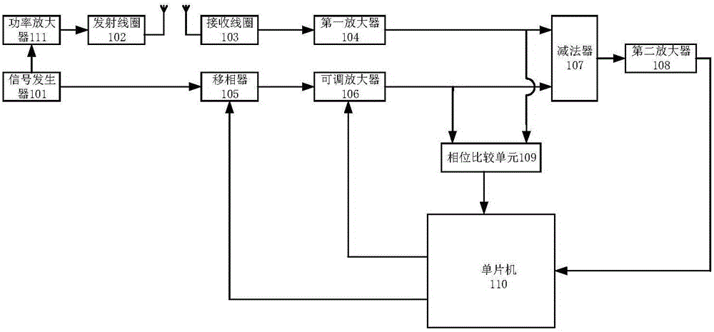
[0091] Please refer to figure 1 , figure 1 It is a block diagram of the first embodiment of the signal amplifying circuit of the present invention. The signal amplifying circuit of the invention can be used in detectors. The detector is a device for detecting metal objects. Detectors include handheld metal detectors and pass-through metal detectors.

[0092] The signal amplifying circuit includes a signal generator 101, a coil branch and a reference branch; wherein the coil branch includes a transmitting coil 102, a receiving coil 103, and a first amplifier 104; the reference branch includes an adjustable amplifier 106; The phase device 105 is set in a branch of the coil branch or the reference branch, and figure 1 In the shown embodiment,...


PUM


Abstract

The invention discloses a signal amplification circuit, a metallic detector formed by the signal amplification circuit and a signal amplification method based on the circuit. The signal amplification circuit comprises a signal generator for generating electromagnetic signals and referential signals, an emission coil for emitting electromagnetic signals, a reception coil for receiving sensed signals, a first amplifier for amplifying output signals of the reception coil, a phase shifter for shifting the phases of the referential signals, an adjustable amplifier for amplifying the referential signals, a phase comparison unit for comparing the output signals of the first amplifier with the output signals of the adjustable amplifier, a subtractor which subtracts the output signals of the adjustable amplifier from the output signals of the first amplifier, a second amplification unit for amplifying the signals output by the subtractor, and a single-chip microcomputer which controls the phase shifter and the adjustable amplifier and receives the output signals of the second amplification unit. The detector formed by the signal amplification circuit has substantially improved detection capability.

Description

technical field [0001] The invention relates to the technical field of metal detectors, in particular to a signal amplifying circuit, a metal detector formed by the circuit and a signal amplifying method based on the circuit. Background technique [0002] Metal detectors are widely used in various fields. Metal detectors will be installed in stations, airports, entertainment venues and other places. Metal detectors detect whether there are metal objects on a person in a non-contact manner. For example, a walk-through metal detector is one of the metal detectors, and the metal detector is equipped with a transmitting coil and a receiving coil inside. When there is metal close to the metal detector, the eddy current effect produced by the metal will affect the magnetic field around the detector. At this time, the receiving coil will generate an induced current, and the voltage will change accordingly. By detecting the voltage change of the receiving coil, it can be judged w...

Claims


Application Information

Patent Timeline
Patent Type & Authority Applications(China)
IPC IPC(8): H03M1/12G01V3/11
CPCH03M1/1245G01V3/10
Inventor 王孝洪王积东陈英杰
Owner DONGGUAN HUADUN ELECTRONICS TECH CO LTD
Why Eureka
Try Eureka