Refrigerator

A technology of refrigerators and evaporators, applied in the field of refrigerators, can solve the problems of incomplete defrosting and excessive frost, and achieve the effect of suppressing abnormal heating

Active Publication Date: 2016-08-10
SHARP KK
View PDF7 Cites 7 Cited by
  • Summary
  • Abstract
  • Description
  • Claims
  • Application Information

AI Technical Summary

Problems solved by technology

In this case, the amount of frost condensed on the evaporator is larger than usual, and the normal defrosting operation cannot completely remove the frost.

Method used


Image

  • Refrigerator
  • Refrigerator
  • Refrigerator

Examples


Embodiment 1

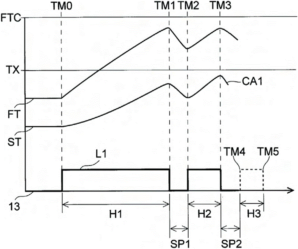
[0063] First, use Figure 4 The flow chart shown and Figure 5The timing chart shown here is for explaining Example 1. Embodiment 1 relates to the first operation function, based on the temperature information that the temperature Te1 of the evaporator 11 detected at the first time (time TM1) after the start of the defrosting operation is lower than the second temperature TA, it is judged that additional defrosting is necessary operation, and drive the defrosting device 13 again. also, Figure 5 0 shown on the vertical axis of , indicates the position of the temperature 0°C, and the first temperature TX is set at 0°C or higher.

[0064] If the defrosting operation starts, the basic defrosting operation of step S1 starts (time TM0). Next, in step S2, it is judged whether the driving duration has reached the first time (time TM1), and when it is judged that the first time has been reached, it advances in the Y direction, and the basic defrosting operation stops (step S4). I...

Embodiment 2

[0077] Next, use Image 6 The flow chart shown and Figure 7 In the timing diagram shown, the embodiment related to the second operation function will be described as Embodiment 2. The above-mentioned second operation function judges the need for evaporator 11 based on the temperature information that the temperature of the evaporator 11 drops after reaching the first time (time TM1). Perform additional defrosting operation and perform drive again. Since the initial process corresponding to the basic defrosting operation process is the same as that of Embodiment 1, the description is omitted, Image 6 Only the additional defrosting operation steps from step S5 to step S8 are shown.

[0078] In the present embodiment, after the basic defrosting operation is stopped (step S4), the temperature Te1 of the evaporator 11 at time TM1 is stored (step S5A). Next, proceed to step S5B, compare the temperature Te2 at time TM2 after a predetermined time has elapsed, that is, after the s...

Embodiment 3

[0089] Next, use Figure 8 The flow chart shown and Figure 9 In the timing diagram shown, the following example will be described as Example 3. When the temperature information indicating that the frost has not completely melted at the end of the extended defrosting operation is detected, it is judged that it is necessary to perform an additional defrosting operation and extend it again. Defrost operation. Figure 8 Only the additional defrosting operation process from the extended defrosting operation of step S6 to the normal control of step S8 is shown.

[0090] After the extended defrosting operation of step S6 starts, in step S6A, judge whether the temperature Te of evaporator is more than the first temperature TX, if " yes ", then advance to Y direction, make extended defrosting operation stop (step S7 ) and return to normal control (step S8).

[0091] If it is "NO" in step S6A, it advances in the N direction, and it is judged whether the drive duration has reached th...


PUM


Abstract

Provided is a refrigerator equipped with a defrosting system with which defrosting can take place in a satisfactory manner while minimizing abnormal heat emission by the defrosting device, and without any loss of ease of use for the user, even in instances in which a large quantity of frost has become deposited on the evaporator. This refrigerator (1) has a basic defrost operation function by which driving of the defrosting device (13) is halted when it is determined that the continuous driving time of the defrosting device (13) has reached a predetermined first time (TM1), and when it is determined that the temperature of the evaporator (11) has reached a predetermined first temperature (TX); and a supplemental defrost operation function by which the necessity for a supplemental defrost operation is determined on the basis of the evaporator (11) temperature information detected when the first time (TM1) has been reached, and driving of the defrosting device (13) is resumed after a predetermined second time (TM2) following the halt has elapsed.

Description

technical field [0001] The present invention relates to a refrigerator having a defrosting device for defrosting an evaporator. Background technique [0002] In the past, refrigerators were equipped with a plurality of storage compartments, including: a refrigerating compartment for storing food and beverages, etc. at a low temperature; Chilling room for fresh food, etc. [0003] In addition, it has an evaporator (cooler) for generating predetermined cold air, a fan and a cold air duct for sending the generated cold air to the freezer compartment, the chiller compartment, and the refrigerator compartment. The cool air supplied through the cool air duct is branched from a plurality of outlets provided on the cool air duct, and flows out into each storage room. [0004] The cool air flowing out to each storage room is returned to the evaporator from each storage room through the return passage. That is, cold air generated by the evaporator circulates in the refrigerator, th...

Claims


Application Information

Patent Timeline
Patent Type & Authority Applications(China)
IPC IPC(8): F25D21/06F25D21/08
CPCF25D21/006F25D2700/10
Inventor 河野卓也出口和広川浪徹
Owner SHARP KK
Why Eureka
Try Eureka