Motor driving circuit and motor driving device

A technology for driving circuits and motors, used in motor control, AC motor control, printed circuits, etc., can solve problems such as difficulty in accurately measuring the current flowing through wiring patterns, and inability to further improve motor rotation control accuracy. Abnormal heat generation and damage, the effect of improving accuracy

Pending Publication Date: 2020-03-31
MITSUMI ELECTRIC CO LTD
View PDF1 Cites 0 Cited by
  • Summary
  • Abstract
  • Description
  • Claims
  • Application Information

AI Technical Summary

Problems solved by technology

[0003] However, the resistance value of the wiring pattern formed on the substrate fluctuates due to individual differences in the substrate, and the temperature characteristics of the wiring pattern also fluctuate, so it is difficult to accurately measure The value of the current of the pattern
Therefore, there is a problem that the accuracy of motor rotation control cannot be further improved in the motor drive circuit that drives the motor based on the value of the current measured using the wiring pattern.

Method used


Image

  • Motor driving circuit and motor driving device
  • Motor driving circuit and motor driving device
  • Motor driving circuit and motor driving device

Examples


Embodiment approach 1

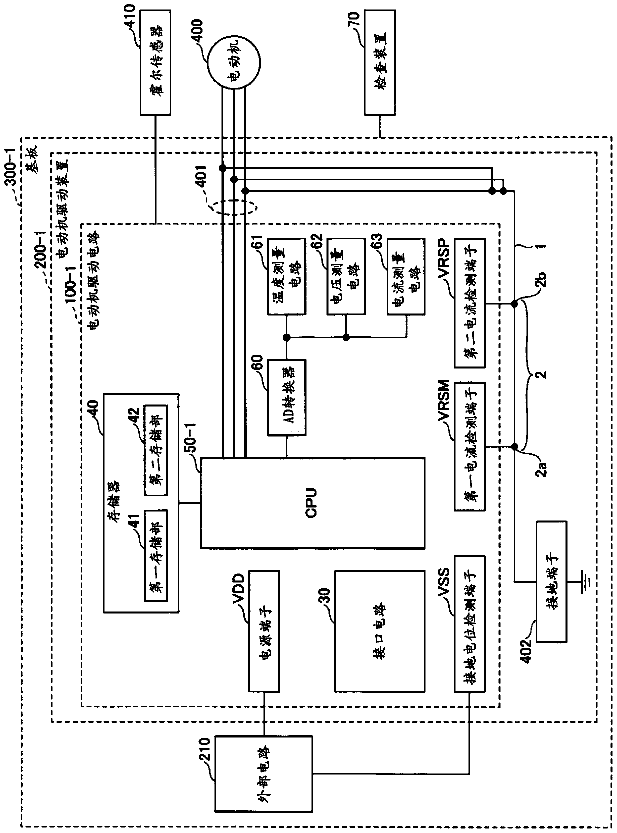
[0020] figure 1 The configuration of the motor drive device according to Embodiment 1 of the present invention is shown. figure 1 The motor drive device 200-1 of Embodiment 1 and the external circuit 210 are provided in the illustrated substrate 300-1. The substrate 300-1 is, for example, a printed circuit board made of glass epoxy resin. The motor drive device 200-1 includes a motor drive circuit 100-1 that measures the current flowing through the wiring pattern 1 formed on the substrate 300-1, and drives the motor based on the measured current value. The wiring pattern 1 is a copper foil pattern formed on the substrate 300-1. One end of the wiring pattern 1 is connected to the motor wiring 401 , and the other end of the wiring pattern 1 is grounded via a ground terminal 402 . One end of the motor wiring 401 is connected to the CPU 50 - 1 , and the other end of the motor wiring 401 is connected to the motor 400 . For example, a three-phase alternating current is transmitt...

Embodiment approach 2

[0046] Figure 7 The configuration of the motor drive device according to Embodiment 2 of the present invention is shown. Hereinafter, the same reference numerals are attached to the same parts as those in Embodiment 1, and description thereof will be omitted, and different parts will be described. exist Figure 7 The motor drive device 200-2 and the external circuit 210 according to Embodiment 2 are provided on the substrate 300-2 shown. The substrate 300-2 is, for example, a printed circuit board made of glass epoxy resin. The motor drive device 200-2 includes a motor drive circuit 100-2 that measures the current flowing through the wiring pattern 1 formed on the substrate 300-2, and drives the motor based on the measured current value.

[0047] The motor drive circuit 100-2 includes an interface circuit 30, a memory 40, a CPU 50-2, an AD converter 60, a temperature measurement circuit 61, a thermistor measurement circuit 61A, a voltage measurement circuit 62, a current m...


PUM


Abstract

The invention provides a motor driving circuit capable of improving accuracy of drive control of a motor and a motor driving device. The motor driving circuit (100-1) includes a current measurement circuit (63) configured to measure an amount of electrical current flowing through a wiring pattern (1), based on an amount of voltage drop caused by the electrical current flowing through a motor (400)flowing through the wiring pattern (1) formed in a substrate (300-1). The motor driving circuit (100-1) includes a drive unit CPU (50-1)configured to adjust a current value, which is a current measurement value, measured by the current measurement circuit (63), based on first adjustment data that compensates for variation in resistance of the wiring pattern (1) caused by an individual differencein the substrate (300-1), and to drive the motor based on an adjusted current value which is the adjusted current measurement value.

Description

technical field [0001] The present invention relates to a motor drive circuit and a motor drive device that measure a current flowing through a wiring pattern formed on a substrate and drive a motor based on the value of the measured current. Background technique [0002] In a motor drive circuit that drives a motor, it is necessary to detect the value of the current flowing through the motor with high precision in order to prevent the influence of the overcurrent of the motor, such as an increase in the rotational speed of the motor and abnormal heat generation of the motor. Patent Document 1 discloses a technique for detecting a voltage drop generated in a specific section of a wiring pattern formed on a substrate, thereby detecting a value of a current flowing through the wiring pattern. [0003] However, the resistance value of the wiring pattern formed on the substrate fluctuates due to individual differences in the substrate, and the temperature characteristics of the ...

Claims


Application Information

Patent Timeline
Patent Type & Authority Applications(China)
IPC IPC(8): H02P25/16H02P29/62
CPCH02P25/16H02P29/62H02P29/64H05K1/0268G01R19/32G01R19/0092G01R35/00H02P21/22H02P29/60H05K1/181H05K2201/1009G01R19/16571H05K2201/10151
Inventor 萩森齐中野一树
Owner MITSUMI ELECTRIC CO LTD
Why Eureka
Try Eureka