
Artificial fish reef with impeller shafts

An artificial reef and impeller shaft technology, which is applied in fish farming, application, climate change adaptation and other directions, can solve the problems of ocean current blocking, single function, easy to block and other problems, and achieve the effects of convenient transportation, simple manufacturing and low cost.

Inactive Publication Date: 2016-08-17
SHANGHAI OCEAN UNIV
View PDF5 Cites 6 Cited by
  • Summary
  • Abstract
  • Description
  • Claims
  • Application Information

AI Technical Summary

Problems solved by technology

[0002] In recent years, although the development of my country's fishery has advanced by leaps and bounds, the traditional marine fishery is still in the extensive stage, with a small scale and relatively low output value. With the rapid development of the fishery, the problems exposed by the fishing industry in the fishery are also increasing. Many, my country's marine environment and fishery resources have been severely damaged under the pressure of continuous high-intensity fishing. In view of the above problems, it is imperative to take measures to improve the marine environment and resources. Among them, artificial fish are placed in the offshore The improvement of the marine ecological environment has achieved good results, and the introduction of artificial reefs has played a very important role in restoring and protecting offshore fishery resources and improving the coastal ecological environment.
[0003] Although there are many kinds of existing artificial reefs, they are mainly aimed at providing places for fishes to breed, grow, bait, and shelter enemies. Therefore, the emergence of thermocline and halocline in the sea area slows down the vertical exchange of water bodies and forms an anoxic layer on the seabed, which easily leads to the death of ginseng and plankton. Therefore, how to improve the upwelling effect of artificial reefs It is a difficult point in artificial reef structure design and technology

Method used


Image

  • Artificial fish reef with impeller shafts
  • Artificial fish reef with impeller shafts
  • Artificial fish reef with impeller shafts

Examples


Embodiment Construction

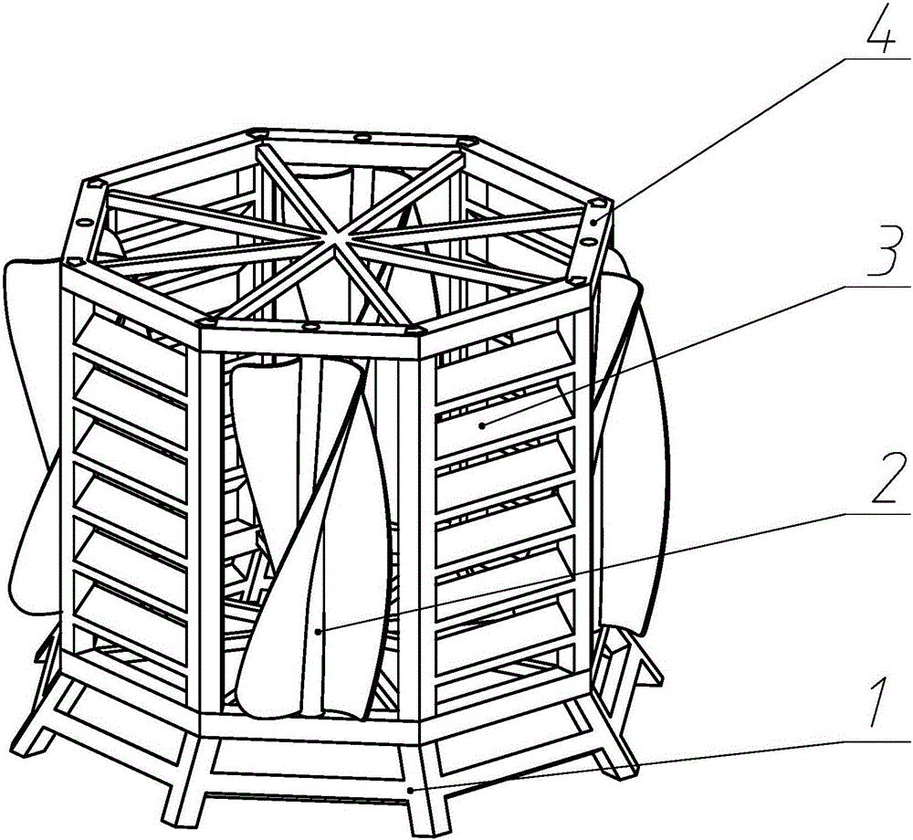
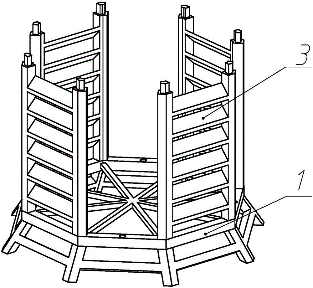
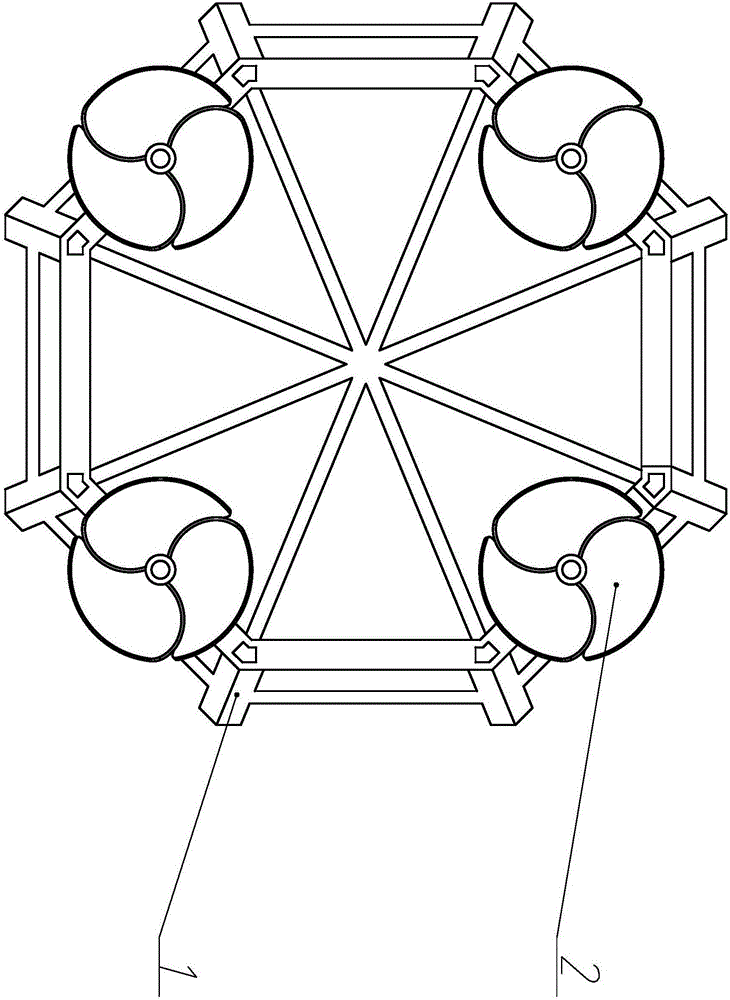
[0015] The artificial reef with impeller shaft of the present invention will be further described in detail below in conjunction with the accompanying drawings.

[0016] see figure 1 , figure 2 , image 3 , the artificial reef with the impeller shaft of the invention comprises an artificial reef body.

[0017] see Figure 4 , the base 1 is composed of an octagonal base frame 11, a "*"-shaped inner support 12, an oblique support foot 13, and a connecting bar 14. A polygonal base assembly hole 111, a circular base connection hole 112 is respectively provided in the middle of the upper end faces of four non-adjacent frame sides among the eight frame sides of the octagonal base frame 11, and the "*" The outer end of the inner support 12 forms a scarf joint with each inner corner of the octagonal base frame 11, and the intersection of adjacent frame sides of the octagonal base frame 11 respectively extends obliquely downward with an oblique support foot 13, corresponding to T...


PUM


Abstract

The invention relates to an artificial fish reef with impeller shafts. The artificial fish reef with the impeller shafts is formed by a base, the impeller shafts, side plates and a top cover, can provide a place for breeding, growing and feeding fishes, meanwhile can effectively produce an upwelling, drives substances such as bottom nutritive salt to exchange with an upper water body, improves the ecological environment in a fish reef sea area, and provides sufficient baits for growing and breeding the fishes. At the same time, the rotation of the impeller shaft can also drive ventilation in the fish reef, and can effectively prevents the blockage of the fish reef during the application process; deflectors arranged on the side plates of the fish reef can also effectively guide an ocean current to flow upwards after passing through the fish reef so as to produce the upwelling, so that the primary productivity in adjacent sea areas of the fish reef is greatly improved.

Description

[0001] The invention relates to an artificial fish reef, in particular to an artificial fish reef with an impeller shaft. Background technique [0002] In recent years, although the development of my country's fishery has advanced by leaps and bounds, the traditional marine fishery is still in the extensive stage, with a small scale and relatively low output value. With the rapid development of the fishery, the problems exposed by the fishing industry in the fishery are also increasing. Many, my country's marine environment and fishery resources have been severely damaged under the pressure of continuous high-intensity fishing. In view of the above problems, it is imperative to take measures to improve the marine environment and resources. Among them, artificial fish are placed in the offshore The artificial reefs have achieved good results in improving the marine ecological environment, and the deployment of artificial reefs has played a very important role in restoring and prot...

Claims


Application Information

Patent Timeline
Patent Type & Authority Applications(China)
IPC IPC(8): A01K61/00
CPCY02A40/81
Inventor 姜少杰刘海敌刘影吴伟杨志乾王董测
Owner SHANGHAI OCEAN UNIV
Learn More