Insect expelling device for lighting lamp

A technology for illuminating lamps and placing boards, which can be used in the fields of trapping or killing insects, applications, animal husbandry, etc. It can solve the problems of complicated operation, incomplete deworming, and low efficiency of deworming, and achieve simple operation and deworming. Thorough and efficient insect repellent

Inactive Publication Date: 2016-08-17
刘小波
0 Cites 2 Cited by

AI-Extracted Technical Summary

Problems solved by technology

[0006] In order to overcome the disadvantages of incomplete insect repellent, low insect repellent efficiency and complicated operation of the existing insect repellent device, the technical prob...

Method used

[0031] Because both the motor I2 and the motor II7 are servo ...

Abstract

The invention relates to an insect expelling device, in particular to an insect expelling device for a lighting lamp, and aims to solve the technical problem of providing an insect expelling device which is relatively thorough in insect expelling, high in insect expelling efficiency and simple in structure, for a lighting lamp. To solve the technical problem, the invention provides the insect expelling device for the lighting lamp. The insect expelling device comprises motors I, electric push rods, long plates, connecting rods II, motors II, a shelving plate, fluorescent powder, support columns, connecting rods I, thumb cylinders, gear racks, gears, sliding tracks, connecting rods III, a trolley and sliding blocks, wherein the trolley is arranged on the ground; the sliding tracks are symmetrically arranged on the left side and the right side at the top of the trolley; the sliding blocks and the connecting rods III are arranged on the sliding tracks; the sliding blocks are positioned above the connecting rods III; the gear racks are mounted on the sliding blocks; the motors I are arranged at the upper ends of the connecting rods III; the gears are connected to the front parts of the motors I; the gears are meshed with the gear racks. The insect expelling device has the effects that insects can be relatively thoroughly expelled, the insect expelling efficiency is high and the structure is simple, and a great amount of labor and materials can be saved.

Application Domain

Insect catchers and killers

Technology Topic

Electric machineryAgricultural engineering +2

Image

  • Insect expelling device for lighting lamp
  • Insect expelling device for lighting lamp
  • Insect expelling device for lighting lamp

Examples

  • Experimental program(1)

Example Embodiment

[0023] Example 1
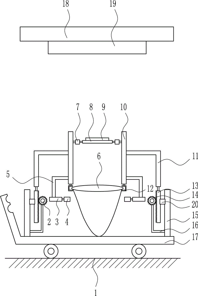
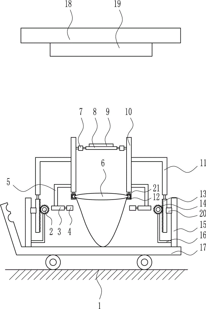
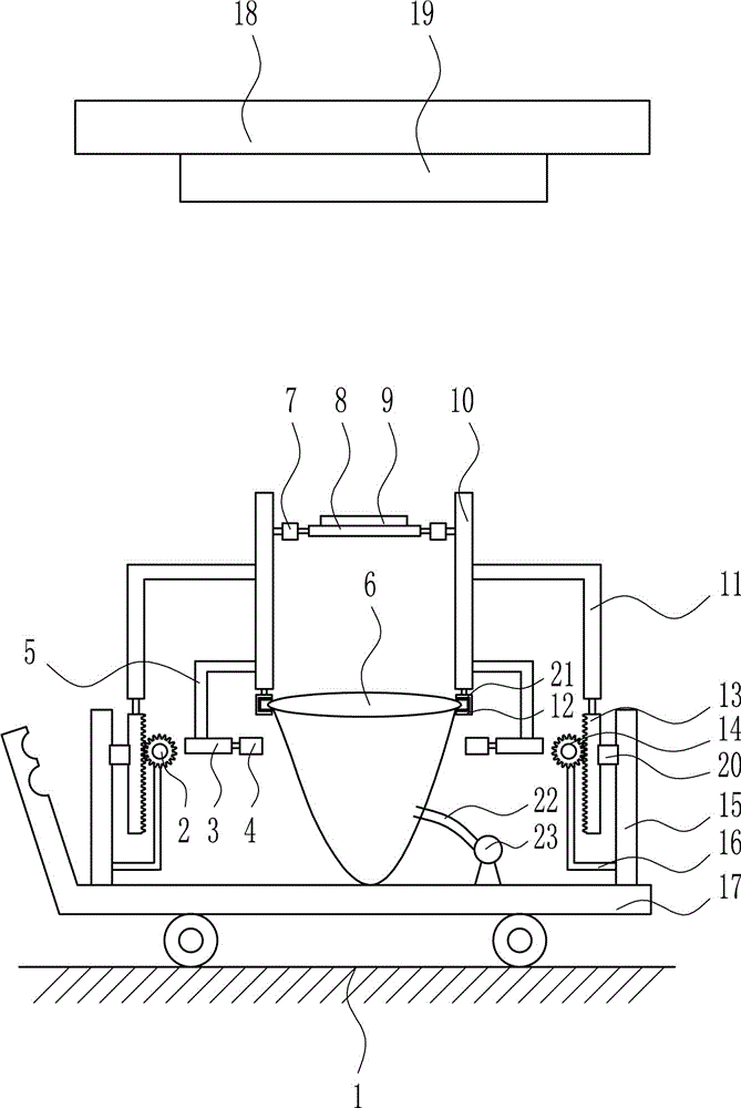
[0024] An insect repellent device for lighting lamps, such as Figure 1-3 As shown, it includes motor I2, electric push rod 3, long plate 4, connecting rod II5, motor II7, placement plate 8, phosphor 9, pillar 10, connecting rod I11, thumb cylinder 12, rack 13, gear 14, Slide rail 15, connecting rod Ⅲ 16, cart 17 and slider 20; there is cart 17 on the ground 1, and the top of cart 17 is provided with slide rails 15 symmetrically on the left and right sides. Slide rail 15 is provided with sliders 20 and connecting blocks. Rod Ⅲ 16, and the sliding block 20 is located above the connecting rod Ⅲ 16, a rack 13 is installed on the sliding block 20, the upper end of the connecting rod Ⅲ 16 is provided with a motor I2, the front of the motor I2 is connected with a gear 14, the gear 14 meshes with the rack 13, and the left and right sides The upper end of the square rack 13 is connected with a connecting rod I11, the connecting rod I11 is connected with a pillar 10, and the upper and inner sides of the pillar 10 are connected with a motor II7. A placement plate 8 is connected between the two motors II7. Phosphor 9, the left and right pillars 10 are provided with connecting rods Ⅱ5 at the lower end, the lower end of the connecting rod Ⅱ5 is provided with an electric push rod 3, the electric push rod 3 is connected with a long plate 4, and the left and right pillars 10 are connected with thumbs at the lower ends The air cylinder 12 is provided with a plastic bag 6 between the two thumb air cylinders 12, a ceiling 18 is provided above the ground 1, and a lighting lamp 19 is provided at the bottom of the ceiling 18.
[0025] A rubber pad 21 is also included, and a rubber pad 21 is provided inside the thumb cylinder 12.
[0026] It also includes a hose 22 and an air pump 23. An air pump 23 is provided on the right side of the top of the cart 17 and a hose 22 is provided on the air pump 23. The left end of the hose 22 is connected to the plastic bag 6.
[0027] Motor Ⅰ2 and motor Ⅱ7 are servo motors.
[0028] Working principle: At first, a person hangs the top ends of the plastic bag 6 in the thumb cylinder 12 respectively, and starts the thumb cylinder 12 to work, so that the thumb cylinder 12 clamps the plastic bag 6. When people turn on the illuminating lamp 19 for use, if mosquitoes are attracted by the strong light of the illuminating lamp 19, the person pushes the cart 17 so that the placement plate 8 is located directly under the ceiling 18, starts the motor I2 to rotate forward, and drives the gear 14 to rotate forward. The rack 13 moves upwards, and the placement plate 8 and the phosphor 9 move upwards accordingly. When the phosphor 9 moves to a suitable position directly under the ceiling 18, the motor I2 stops working, and the lighting 19 irradiates the phosphor 9 for a period of time and then turns off The illuminating lamp 19, but the phosphor 9 will still produce light to attract mosquitoes due to the illumination of the illuminating lamp 19. Start the motor Ⅱ7 to rotate 180°, drive the placing plate 8 to rotate 180°, the motor Ⅱ7 stops working, so that the phosphor 9 on the placing plate 8 falls into the plastic bag 6, and the mosquitoes enter the plastic bag 6 along with the phosphor 9. When 9 and the mosquitoes completely fall into the plastic bag 6, start the motor Ⅱ7 to rotate 180°, drive the placement plate 8 to rotate 180° to reset, and the motor Ⅱ7 stops working. The electric push rod 3 is started to extend, so that the long plates 4 on both sides move toward each other. When the long plates 4 on both sides approach each other, the electric push rod 3 stops extending. At this time, the long plate 4 closes the plastic bag 6, the thumb cylinder 12 stops working, and the person removes the plastic bag 6 and throws it into the trash can. Start the electric push rod 3 to shorten, drive the long plates 4 on both sides to reset, and the electric push rod 3 stops shortening. The motor I2 is started to reverse, and the gear 14 is driven to reverse, so that the rack 13 is driven to move downward, and the placement plate 8 moves downward to reset, and the motor I2 stops working.
[0029] Because it also includes a rubber pad 21, the thumb cylinder 12 is provided with a rubber pad 21 inside, so when the thumb cylinder 12 clamps the plastic bag 6, the rubber pad 21 can protect the plastic bag 6 and prevent the plastic bag 6 from being damaged and mosquitoes flying out.
[0030] Because it also includes a hose 22 and an air pump 23, an air pump 23 is provided on the right side of the top of the cart 17, and a hose 22 is provided on the air pump 23. The left end of the hose 22 is connected to the plastic bag 6, so when the long plate 4 When the plastic bag 6 is closed, the air pump is started to pump the air in the plastic bag 6 through the hose 22, so that the plastic bag 6 is in a vacuum state, and the mosquitoes die due to lack of oxygen.
[0031] Because both motor Ⅰ2 and motor Ⅱ7 are servo motors, the speed can be controlled more accurately.

PUM

no PUM

Description & Claims & Application Information

We can also present the details of the Description, Claims and Application information to help users get a comprehensive understanding of the technical details of the patent, such as background art, summary of invention, brief description of drawings, description of embodiments, and other original content. On the other hand, users can also determine the specific scope of protection of the technology through the list of claims; as well as understand the changes in the life cycle of the technology with the presentation of the patent timeline. Login to view more.

Similar technology patents

Graphene film and preparation method therefor

Owner:CHANGZHOU FUXI TECH CO LTD

Driving working load calculation method of automobile driver

InactiveCN101690666AImprove accuracy and timelinessEasy to operate
Owner:BEIJING UNIV OF TECH

Multi-frequency generator with good stability

ActiveCN109619085AImprove job stabilityImprove insect repellent efficiency
Owner:北京吉安驰科技有限公司

Classification and recommendation of technical efficacy words

  • Improve insect repellent efficiency

Multi-frequency generator with good stability

ActiveCN109619085AImprove job stabilityImprove insect repellent efficiency
Owner:北京吉安驰科技有限公司
Why Eureka
Try Eureka