

Dehumidification device of power cabinet
A technology for power cabinets and isolation frames, which is applied to substation/distribution device casings, gas treatment, membrane technology, etc., can solve problems such as corrosion of power equipment terminals, reduced insulation performance, and loss of power failure accidents, and achieves a simple structure for dehumidification devices. , prolong the service life and prevent corrosion
- Summary
- Abstract
- Description
- Claims
- Application Information
AI Technical Summary
Problems solved by technology
Method used
Image

Examples
Embodiment Construction
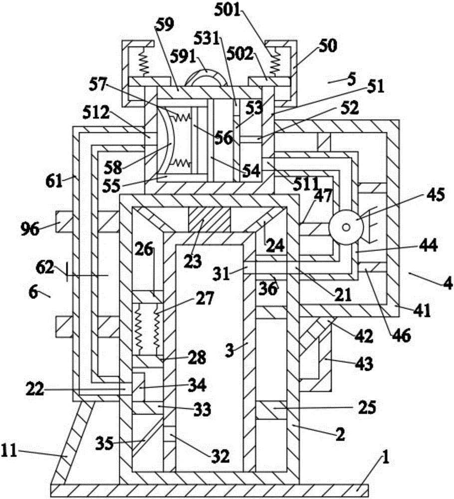
[0019] Such as figure 1 As shown, the power cabinet dehumidification device of the present invention includes a base plate 1, an isolation frame 2 located above the base plate 1, a power cabinet 3 located in the isolation frame 2, an air extraction device 4 located on the right side of the isolation frame 2, The drying device 5 above the isolation frame 2 and the pipeline device 6 on the left side of the drying device 5 .
[0020] Such as figure 1 As shown, the base plate 1 is a cuboid, the base plate 1 is placed horizontally, the base plate 1 is placed on the ground, the base plate 1 is provided with a first slanting bar 11, and the first slanting bar 11 is inclined. The lower end of the first slanting rod 11 is fixedly connected with the bottom plate 1 .
[0021] Such as figure 1As shown, the isolation frame 2 is a hollow cuboid, and the lower surface of the isolation frame 2 is fixedly connected with the upper surface of the bottom plate 1 . The isolation frame 2 is pro...
PUM
 Abstract
Description
Claims
Application Information