
Pneumatic stirring apparatus and preparation method of magnetic suspension

A technology of pneumatic stirring and magnetic suspension, applied in chemical instruments and methods, mixer accessories, transportation and packaging, etc., can solve the problems of low inspection efficiency, high concentration of magnetic suspension in the bottom layer, and failure to achieve complete uniformity of magnetic suspension concentration, etc. , to achieve the effect of improving the detection rate and ensuring the inspection effect

Inactive Publication Date: 2016-08-17
KOCEL STEEL
View PDF3 Cites 6 Cited by
  • Summary
  • Abstract
  • Description
  • Claims
  • Application Information

AI Technical Summary

Problems solved by technology

[0003] In the magnetic particle flaw detection of small steel castings, the method of manually preparing magnetic suspension with a small watering can is generally used, but this method requires a small amount of magnetic suspension each time, and frequent configuration of magnetic suspension is required, resulting in low inspection efficiency.
When performing magnetic particle flaw detection on large steel castings, a mechanical propeller stirring mechanism is generally used to configure the magnetic suspension. However, due to the limitation of the stirring principle of this stirring device, the bottom of the stirring tank will settle more magnetic powder, resulting in the bottom of the magnetic suspension. The concentration is high, and it cannot meet the requirement that the concentration of the magnetic suspension in the entire mixing tank is completely uniform

Method used


Image

  • Pneumatic stirring apparatus and preparation method of magnetic suspension

Examples


Embodiment Construction

[0020] The following will clearly and completely describe the technical solutions in the embodiments of the present invention with reference to the accompanying drawings in the embodiments of the present invention. Obviously, the described embodiments are some of the embodiments of the present invention, but not all of them. Based on the embodiments of the present invention, all other embodiments obtained by persons of ordinary skill in the art without creative efforts fall within the protection scope of the present invention.

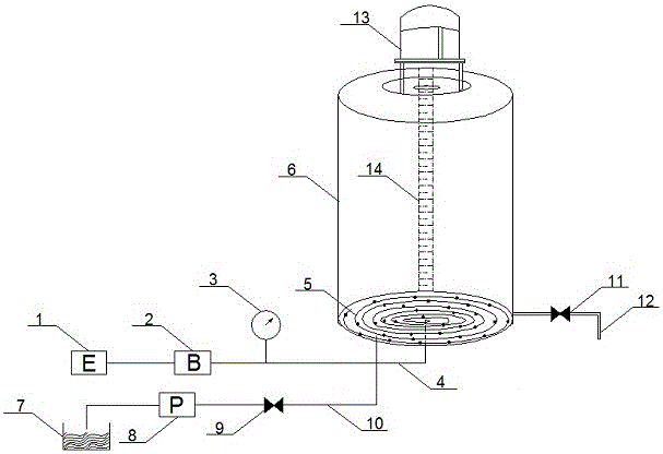
[0021] Such as figure 1 As shown, the embodiment of the present invention provides a pneumatic stirring device, which may include a pneumatic stirring mechanism, a mixing mechanism and a measuring mechanism for measuring the water level. The pneumatic stirring mechanism includes a motor 1, a blower 2, an air gauge 3, and an air intake hose 4. The spiral intake pipe 5, the motor 1 is connected to the blower 2, the blower 2 is connected to the spiral int...


PUM


Abstract

A pneumatic stirring device comprises a pneumatic stirring mechanism, a mixing mechanism and a measuring mechanism, the pneumatic stirring mechanism comprises a motor, a blower, a gas pressure meter, an intake hose and a spiral intake pipe, the motor is connected to the blower, the blower is connected to the spiral intake pipe through the intake hose, the spiral intake pipe is provided with air inlets, and the intake hose is fitted with the gas pressure meter; the mixing mechanism comprises a stirring barrel, a water storage pool, a water pump, an inflow valve, an inflow pipe and an outflow pipe, the spiral intake pipe is positioned at the inner bottom of the stirring barrel, the intake hose passes through a sidewall of the stirring barrel into the stirring barrel, the inflow pipe connects the water storage pool with the stirring barrel, the inflow pipe is fitted with the water pump and the inflow valve for controlling water inflow, the bottom of the stirring barrel is fitted with the outflow pipe, the outflow pipe is fitted with the outflow valve, and a feed port is provided above the stirring barrel; the measuring mechanism includes a water level scale placed in the stirring barrel. An embodiment of the invention also provides a preparation method of a magnetic suspension.

Description

technical field [0001] The invention relates to the mechanical field, in particular to a pneumatic stirring device and a preparation method of a magnetic suspension. Background technique [0002] Magnetic particle testing is a kind of non-destructive testing, which is used to detect defects on the surface and near the surface of the workpiece: without destroying the structure and performance of the test object, after the ferromagnetic material and the workpiece are magnetized, due to the existence of discontinuity, the workpiece The magnetic field lines on the surface and near the surface are locally distorted to generate a leakage magnetic field, which can absorb the magnetic powder in the magnetic suspension liquid sprayed on the surface of the workpiece and form visually visible magnetic marks under suitable light, thus showing discontinuous positions, shapes and size. In order to ensure that the magnetic powder particles in the magnetic suspension sprayed on the surface...

Claims


Application Information

Patent Timeline
IPC IPC(8): B01F13/02B01F15/00G01N27/84B01F33/40
CPCG01N27/84B01F33/406B01F35/2112B01F2101/23
Inventor 李磊拓凌玺鲁海洋马文治征立刚李飞苏星星李阳
Owner KOCEL STEEL
Learn More