
Welding locating device for perforated part and boss

A technology of welding positioning and bosses, which is applied in the direction of auxiliary devices, welding equipment, auxiliary welding equipment, etc., can solve problems such as difficult concentricity and positioning of bosses with holes and angle adjuster holes, no welding positioning, and high labor intensity. Achieve high concentricity, convenient positioning, and low labor intensity

Active Publication Date: 2016-08-17
ZHEJIANG LONGSHENG AUTO PARTS TECH CO LTD
View PDF10 Cites 4 Cited by
  • Summary
  • Abstract
  • Description
  • Claims
  • Application Information

AI Technical Summary

Problems solved by technology

The disadvantage of this method is that the boss with holes and the hole of the angle adjuster are not easy to be concentric and positioned, and its work efficiency is low and the labor intensity is high.
Its disadvantage is that it is only a workpiece self-positioning and clamping device, and does not have the function of welding with other parts after it is positioned, that is, it is only suitable for self-positioning and clamping of workpieces, without the function of welding positioning and purpose, nor its structure
[0004] Chinese invention patent application number 2015104643832 discloses a "positioning device for cylindrical parts with holes", which uses a manipulator to clamp cylindrical parts to realize automatic loading and unloading, automatic assembly, and fully automated production operations; but it does not It is not suitable for the function of welding a boss with a hole on its upper surface after positioning the mechanical part with a hole

Method used


Image

  • Welding locating device for perforated part and boss
  • Welding locating device for perforated part and boss
  • Welding locating device for perforated part and boss

Examples


Embodiment Construction

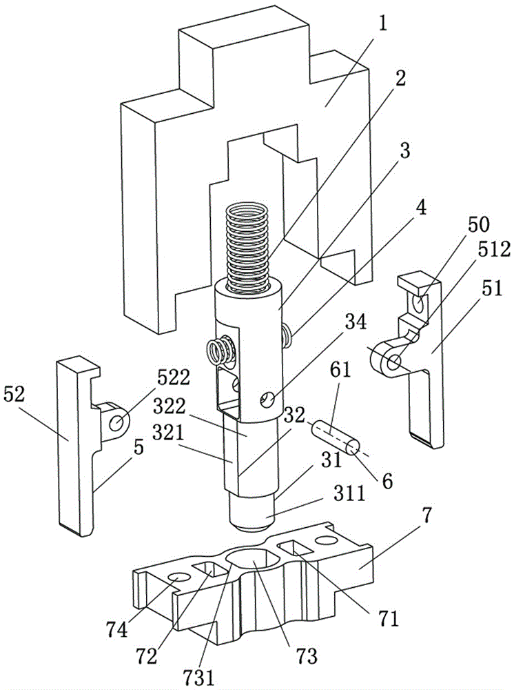
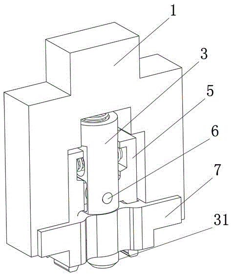
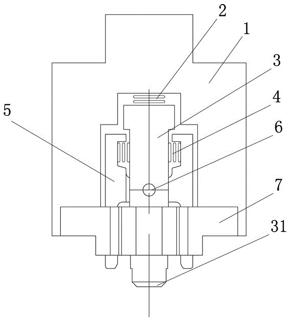
[0021] see Figure 1 ~ Figure 4 , the present invention includes a base 1, a positioning shaft 3, a fixed block 7 and two corresponding clamping arms 5; the clamping arm 5 is composed of left and right clamping arms 52, 51, and the positioning shaft 3 is located Between the right clamping arms 52, 51 and connected with the left and right clamping arms 52, 51; the fixed block 7 is located at the bottom of the machine base 1 and is connected with the machine base 1, and the positioning shaft 3 and the clamping arm 5 are all located at the machine base 1 and between the fixed block 7.

[0022] The present invention has a fixed block middle hole 73 in the middle of the fixed block 7, and symmetrical left and right side holes 72, 71 are respectively opened on both sides of the fixed block middle hole 73, and the fixed block middle hole 73 and the left and right sides The holes 72 and 71 are through holes; the left and right clamping arms 52 and 51 are respectively located in the l...


PUM


Abstract

The invention relates to a welding locating device for a perforated part and a boss. The welding locating device is specially used for locating the perforated mechanical part so that the perforated boss can be welded to the perforated part after hole locating. The welding locating device is characterized by being provided with a locating shaft, a fixing block and two corresponding clamping arms, and the locating shaft, the fixing block and the two clamping arms are matched; the fixing block is provided with a fixing block middle hole and symmetrical side holes, and the clamping arms are located inside the side holes respectively; the locating shaft is provided with a front section and a middle section, the front section and the middle section are coaxial and are located in the fixing block middle hole, and a containing space is formed among the middle section, the fixing block and the two clamping arms. The welding locating device is reasonable in structural design, the concentricity of the perforated boss and the perforated part can be guaranteed by placing the perforated boss to be welded on the welding locating device in a sleeving mode and arranging the perforated boss at the position of the perforated part, the perforated part and the perforated boss can be located conveniently and accurately, the concentricity is high, and the quality of welded products is high; in addition, the work efficiency is high, and the labor intensity is low.

Description

technical field [0001] The present invention relates to a kind of mechanical equipment, especially a kind of welding positioning device for bosses with holes, which is specially used for positioning mechanical parts with holes, so as to weld bosses with holes around them after the holes are positioned; that is, it is A positioning device for welding a small boss with holes and other large parts with holes to ensure that the holes are concentric with each other. Background technique [0002] In the prior art, the method used to weld the boss with holes, that is, the small boss with holes, and other parts with holes, that is, large parts with holes, to ensure that the holes are concentric with each other is as follows: first, ensure that the small parts with holes If the hole is larger than the hole of the large part to be welded, the large part must be positioned on the tooling, and then the small part with holes is placed on the large part, and the large hole of the small pa...

Claims


Application Information

Patent Timeline
Patent Type & Authority Applications(China)
IPC IPC(8): B23K37/04
CPCB23K37/0443
Inventor 俞龙生
Owner ZHEJIANG LONGSHENG AUTO PARTS TECH CO LTD
Learn More