Clamping tool favorable for uniform distribution of clamping force

A technology for uniform distribution and clamping tools, which is applied in the direction of manufacturing tools, vises, etc., can solve the problems of damage to the dimensional accuracy of parts and uneven force, and achieve the effect of uniformity and matching accuracy

Inactive Publication Date: 2016-08-17
CHENGDU HENGTONG ZHAOYE PRECISION MACHINERY
View PDF7 Cites 5 Cited by
  • Summary
  • Abstract
  • Description
  • Claims
  • Application Information

AI Technical Summary

Problems solved by technology

[0004] In the above-mentioned prior art, for parts with high dimensional accuracy, when the parts are clamped by the bench vise without using other cushioning objects to wrap the parts, the force on the jaws of the bench vise is uneven at different positions. It is easy to cause the problem that the dimensional accuracy of the parts is damaged. The invention provides a clamping tool that is beneficial to the uniformity of the clamping force distribution

Method used


Image

  • Clamping tool favorable for uniform distribution of clamping force

Examples


Embodiment 1

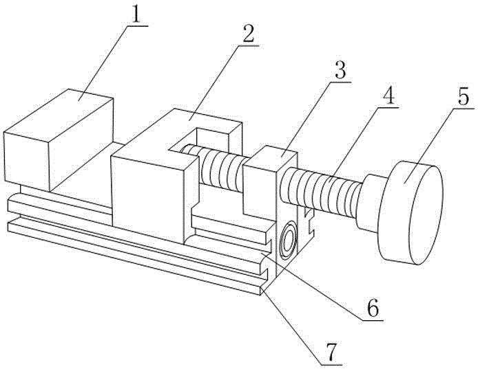
[0021] Such as figure 1 As shown, a clamping tool that is beneficial to the uniformity of clamping force distribution includes a bottom plate 7, a fixed block 1, a movable block 2 and a pushing device for pushing the movable block 2 to move toward the side of the fixed block 1, The base plate 7 is strip-shaped, and the fixed block 1 is fixed on one end of the base plate 7. The pushing direction of the pushing device is along the length direction of the base plate 7, and both sides of the base plate 7 are provided with slides along the length direction of the base plate 7. Groove 6, two sliders that are respectively matched with different chute 6 are arranged on the movable clamping block 2, and the mating surface formed by the side of the chute 6 and the bottom surface of the slider is an arc surface, and in the chute 6 in the depth direction, the highest point of the arc surface is located between the opening end of the chute 6 and the bottom end of the chute 6 .

[0022] Sp...

Embodiment 2

[0025] The present embodiment is further limited on the basis of embodiment 1, as figure 1 As shown, as a simple implementation form of the pusher, the pusher includes a threaded rod 4, a threaded seat 3 and a handle 5, the threaded seat 3 is fixed on the bottom plate 7, and the threaded rod 4 is threaded with the threaded seat 3 , the axial direction of the threaded rod 4 is parallel to the length direction of the bottom plate 7, the turning handle 5 is fixed on the threaded rod 4, and the movable block 2 is located between the fixed block 1 and the pushing device. In the above structure, during the rotation of the threaded rod 4 , the end of the threaded rod 4 exerts a driving force on the movable block 2 , and the rotating handle 5 is used to drive the threaded rod 4 to rotate.

[0026] As a specific implementation scheme with a loosening function, the threads on the threaded rod 4 and the threaded seat 3 are both fine threads.

[0027] In order to prevent debris from ente...


PUM


Abstract

The invention discloses a clamping tool which is beneficial to the uniformity of the clamping force distribution, comprising a base plate, a fixed block, a movable block and a pushing device for pushing the movable block to move toward the side of the fixed block, the bottom plate is strip-shaped , the fixed block is fixed on one end of the bottom plate, the pushing direction of the pushing device is along the length direction of the bottom plate, both sides of the bottom plate are provided with chute along the length direction of the bottom plate, and the movable block is provided with Two sliders that are matched with different chute respectively, the mating surface formed by the side of the chute and the bottom surface of the slider is an arc surface, and in the depth direction of the chute, the highest point of the arc surface is at Between the open end of the chute and the bottom end of the chute. When the parts are clamped, the structure is beneficial to the uniformity of force on each point on the clamping surface and to the stability of the relative positions of the fixed clamping block and the movable clamping block.

Description

technical field [0001] The invention relates to the field of mechanical processing equipment, in particular to a clamping tool that facilitates the uniform distribution of clamping force. Background technique [0002] In the process of mechanical manufacturing, the device used to fix the processing object so that it occupies the correct position to accept construction or inspection is generally called a fixture, also known as a jig. In a broad sense, any process in the process of workpiece production, inspection or maintenance, the device used to quickly, conveniently and safely install the workpiece can be called a fixture. Such as welding fixtures, inspection fixtures, assembly fixtures, machine tool fixtures, etc. [0003] In the prior art, a bench vise is a kind of universal fixture, and is an indispensable clamping device on a fitter's bench. Although the bench vise can clamp larger workpieces and provide sufficient clamping force, for parts with high dimensional accu...

Claims


Application Information

Patent Timeline
IPC IPC(8): B25B1/10
CPCB25B1/10
Inventor 吴光武
Owner CHENGDU HENGTONG ZHAOYE PRECISION MACHINERY
Why Eureka
Try Eureka