Low-temperature plasma waste gas treatment system

A low-temperature plasma and waste gas treatment technology, used in gas treatment, separation methods, dispersed particle separation, etc., can solve the problems of easy corrosion of equipment, high operating costs, no degradation effect, etc., to achieve uniformity and increase sweeping area. , Improve the effect of purification efficiency

Pending Publication Date: 2018-08-14
NINGBO UNIV
View PDF0 Cites 2 Cited by
  • Summary
  • Abstract
  • Description
  • Claims
  • Application Information

AI Technical Summary

Problems solved by technology

The actual operating cost of the activated carbon adsorption method is relatively high, the replacement of activated carbon, desorption and secondary treatment are troublesome, the treatment effect is difficult to guarantee for a long time and monitored at any time, and there may be a variety of factors that cannot coexist, causing exothermic reactions and oxidation in the activated carbon bed. Polymerization reaction, with the continuous increase of the concentration, there are certain unsafe factors; the equipment used in the catalytic combustion method is easy to corrode, and the gas with low concentration needs to consume fuel and the treatment cost is high, the catalyst is easy to be poisoned, and at the same time, it is easy to form such as dioxin Secondary pollution, etc.; while the by-products produced by the absorption method need subsequent treatment, there is no actual degradation effect on insoluble or slightly soluble gases, the price of the absorbent is high, it is not easy to regenerate, and the operating cost is high; biological filtration treatment is harmful to all The organic factors for degradation are selective, biodegradation generally requires a long residence time, and there are certain requirements for the collection of waste gas and construction sites. The stability of degradation has yet to be investigated, and there are also certain problems in terms of comprehensive costs.

Method used


Image

  • Low-temperature plasma waste gas treatment system
  • Low-temperature plasma waste gas treatment system
  • Low-temperature plasma waste gas treatment system

Examples


Embodiment 1

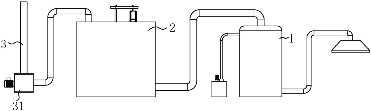
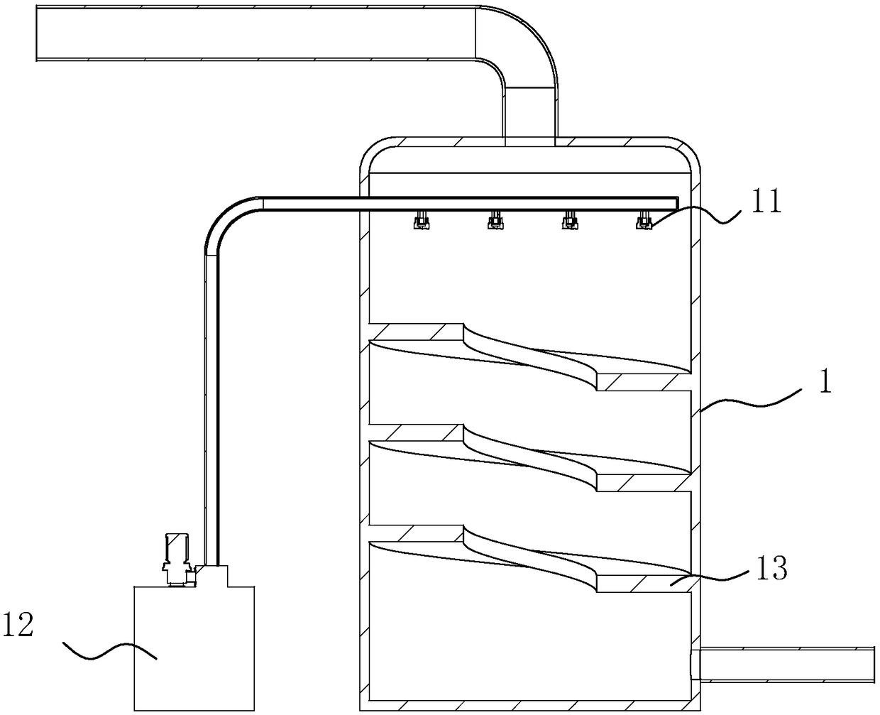
[0039] as attached figure 1As shown, a low-temperature plasma waste gas treatment system includes a spray tower 1 , a plasma purification device 2 and a chimney 3 . Here, the position near the bottom of the spray tower 1 communicates with an exhaust gas absorption hood, and the top of the spray tower 1 communicates with the side near the bottom of the plasma purification device 2, and the top of the plasma purification device 2 communicates with the chimney 3 The exhaust fan 31 is connected.

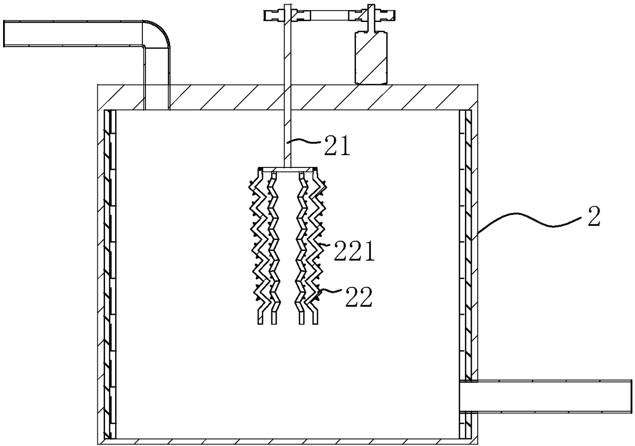
[0040] Among them, as attached figure 2 As shown, a rotating shaft 21 is pierced at the center of the top of the plasma purification device 2 , and the upper end of the rotating shaft 21 is connected to a motor outside the plasma purification device 2 . The rotating shaft 21 can be driven by the motor to rotate. At the same time, the lower end of the rotating shaft 21 is hinged with a number of probes 22 along the radial direction of the rotating shaft 21, and the probes 22 can be fl...

Embodiment 2

[0046] as attached Figure 4 As shown, a low-temperature plasma exhaust gas treatment system is based on the first embodiment, and the top of the plasma purification device 2 also has a number of spray holes 23, and the spray holes 23 communicate with the external liquid storage tank 24. The solution in the liquid storage tank 24 is an alkaline hydrogen peroxide solution, which is conducive to improving the preservation of hydrogen peroxide and reducing the decomposition rate of hydrogen peroxide. When the alkaline hydrogen peroxide solution is sprayed down, the probe 22 will splash the alkaline hydrogen peroxide solution in the process of rotation, which can speed up the purification of the exhaust gas.

[0047] In addition, when the exhaust gas enters the plasma purification device 2, the exhaust gas will be oxidized and decomposed to produce carbon dioxide and water, which will be absorbed by the alkaline hydrogen peroxide, so that the pH value of the alkaline hydrogen pero...

Embodiment 3

[0050] as attached Figure 5 As shown, a low-temperature plasma exhaust gas treatment system is based on the second embodiment, and an activated carbon adsorption device 4 is also arranged between the plasma purification device 2 and the chimney 3 . Among them, as attached Figure 6 As shown, the air inlet of the activated carbon adsorption device 4 has several baffles 41 inclined downwards, and the baffles 41 are arc-shaped. In this way, the exhaust gas after passing through the plasma purification device 2 will first pass through the baffle plate 41, and the water mist in the exhaust gas will condense on the baffle plate 41 during this process, and flow down along the baffle plate 41, thereby effectively improving the baffle plate. 41 service life. Thereby reducing the water content in the exhaust gas, which is beneficial to ensure that the activated carbon is in a dry state for a long time, and then helps to ensure the adsorption performance of the activated carbon for a ...


PUM


Abstract

The application discloses a low-temperature plasma waste gas treatment system, and mainly relates to the field of waste gas treatment. The low-temperature plasma waste gas treatment system comprises asprinkling tower, a plasma purifying device and a chimney which are connected in sequence in a communicating manner; a plurality of probes which are connected with a negative electrode of a power supply are arranged in the centre of the top of the plasma purifying device, and the probes are uniformly distributed in a circle; the inner wall of the plasma purifying device is connected with a positive electrode of the power supply. By adopting the technical scheme, when the probes and the inner wall of the plasma purifying device are energized, an electric field can be produced between the probes and the inner wall of the plasma purifying device, and the electric field can convert nearby VOCs (Volatile Organic Compounds) into non-toxic harmless gases, such as carbon dioxide and water vapour.In addition, if the waste gas still carries with oil stain gas, the oil stain can be adsorbed on the surfaces of the probes and flow to the bottom of the plasma purifying device along the probes. Therefore, the cleaning of a worker to oil stain is facilitated.

Description

technical field [0001] The invention relates to the field of exhaust gas treatment, in particular to a low-temperature plasma exhaust gas treatment system. Background technique [0002] VOCs are volatile organic compounds, which are a kind of common air pollutants. They mainly come from the exhaust gas emitted by factories. They are commonly found in paint production, chemical fiber industry, metal coating, chemical coatings, shoemaking and tanning, electroplating, plywood manufacturing, tires Manufacturing, wastewater treatment plants and other industries. Harmful volatile organic compounds mainly include acetone, toluene, phenol, dimethylaniline, formaldehyde, n-hexane, ethyl acetate, ethanol, etc. [0003] According to the national industrial waste gas emission standards, industrial waste gas must meet its emission standards when discharged, which requires corresponding treatment of VOCs in industrial waste gas during the discharge process. The traditional treatment meth...

Claims


Application Information

Patent Timeline
IPC IPC(8): B01D53/32B01D53/78B01D53/72B01D53/62
CPCB01D53/323B01D53/62B01D53/72B01D53/78B01D2259/818B01D2257/708B01D2257/504B01D2251/106Y02A50/20
Inventor 竺新波
Owner NINGBO UNIV
Why Eureka
Try Eureka