
Movement control method for six-shaft industrial robot of specific structure

A technology of industrial robots and motion control, applied in the direction of program control manipulators, manipulators, manufacturing tools, etc., can solve the problems of complex calculation process, inability to calculate inverse solutions, and inability to eliminate elements.

Active Publication Date: 2016-08-17
GUANGZHOU ZSROBOT INTELLIGENT EQUIP CO LTD
View PDF6 Cites 13 Cited by
  • Summary
  • Abstract
  • Description
  • Claims
  • Application Information

AI Technical Summary

Problems solved by technology

The biggest disadvantage of the algebraic method is that the calculation process is complicated. Since most of the calculations are based on matrix calculations, errors are prone to occur during the calculation process. In addition, the calculation results of the algebraic method are affected by the DH parameters of the robot rod. If If the DH parameter of the member is not selected correctly, it will not be possible to eliminate the elements, resulting in the inverse solution not being calculated at the end
Compared with the previous two algorithms, the geometric method is simpler, and the whole process is calculated based on geometric figures, which is more intuitive. However, there are relatively few relevant literatures on the inverse solution of the geometric method in the current technology, especially for various configurations. Industrial robots lack corresponding inverse data, so it is impossible to effectively control the motion of industrial robots

Method used


Image

  • Movement control method for six-shaft industrial robot of specific structure
  • Movement control method for six-shaft industrial robot of specific structure
  • Movement control method for six-shaft industrial robot of specific structure

Examples


Embodiment Construction

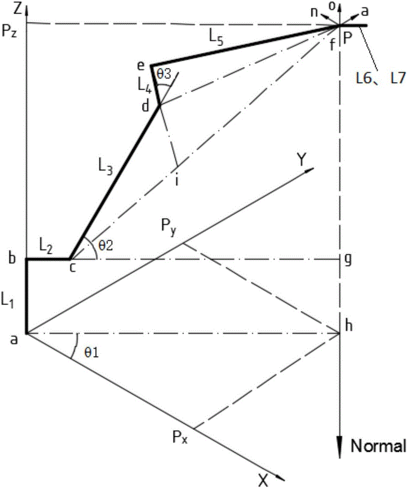
[0054] The invention provides a motion control method for a six-axis industrial robot with a specific configuration, comprising the following steps:

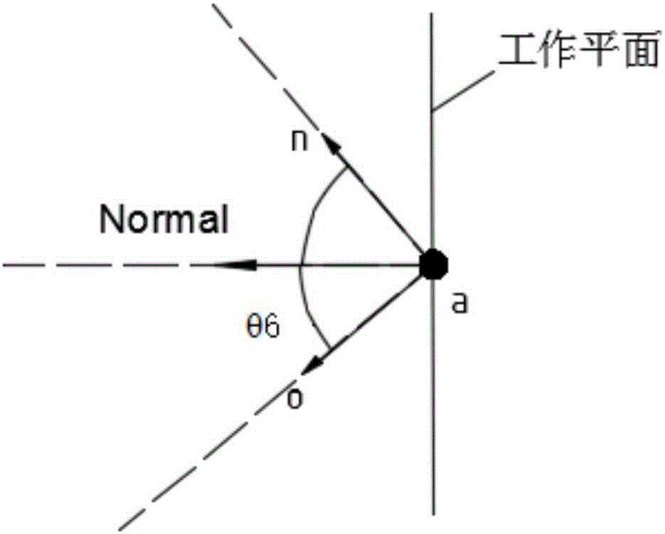
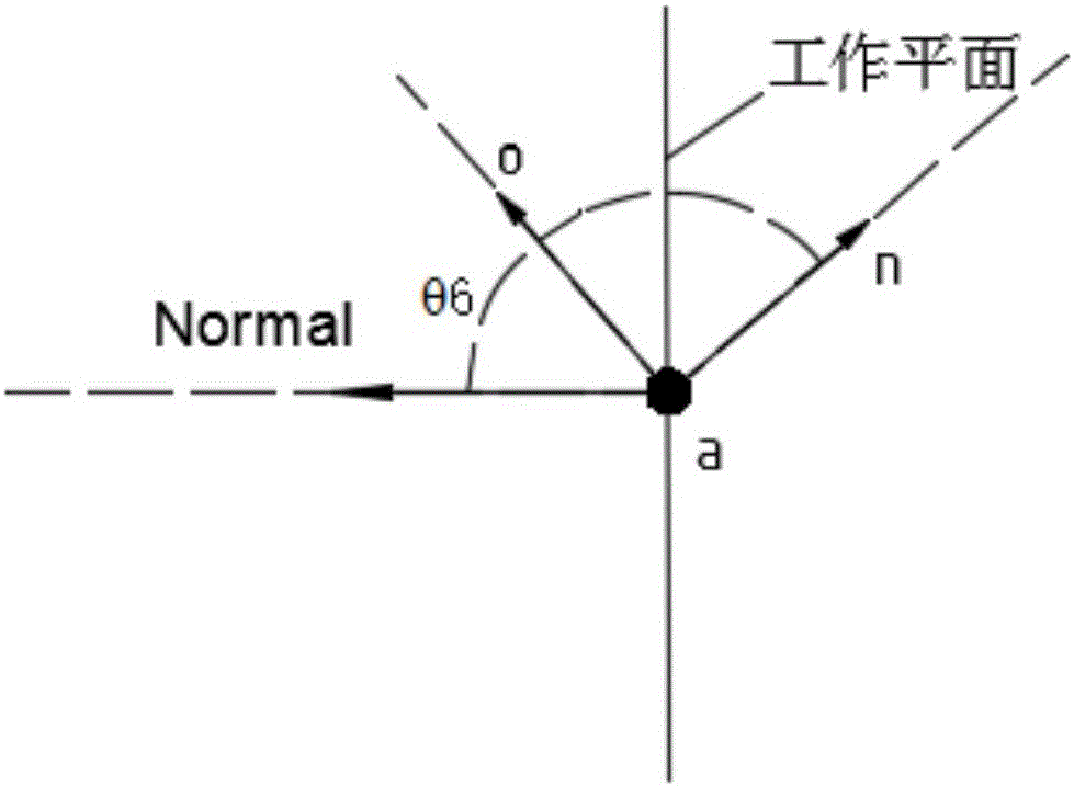
[0055] S1. Establish the connecting rod coordinate system of the industrial robot, and obtain the geometric relationship between the seven rods and the six axes of the industrial robot;

[0056] S2. After obtaining the G command file corresponding to the industrial robot, read the target motion position of the industrial robot;

[0057] S3. According to the target motion position and the geometric relationship of the industrial robot, sequentially calculate the joint angles of the six axes of the industrial robot;

[0058] S4. After converting the calculated six joint angles into the number of motion pulses corresponding to each axis, send them to the driver of the industrial robot;

[0059] S5. The driver sequentially drives the corresponding motors to drive the corresponding axes to move according to the number of motion puls...


PUM


Abstract

The invention discloses a movement control method for a six-shaft industrial robot of a specific structure. The movement control method for the six-shaft industrial robot of the specific structure comprises the steps that a connecting-rod coordinate system of the industrial robot is established, and the geometrical relationship between seven connecting rod pieces and six shafts of the industrial robot is obtained; after a G command file corresponding to the industrial robot is obtained, the target movement position of the industrial robot is read; the joint angles of the six shafts of the industrial robot are calculated in sequence according to the target movement position and the geometrical relationship of the industrial robot; after the calculated six joint angles are converted into the movement pulse numbers corresponding to the six shafts, the movement pulse numbers of the six shafts are sent to a driver of the industrial robot; the driver sequentially drives corresponding motors to drive the corresponding shafts to move. According to the movement control method, the inverse solution of the movement of the industrial robot is conducted based on the geometrical relationship, so that movement control of the industrial robot is achieved; the operating rate is high, the calculation efficiency is high, and the control efficiency is high; and the movement control method for the six-shaft industrial robot of the specific structure can be widely applied to the field of control over industrial robots.

Description

technical field [0001] The invention relates to the control field of industrial robots, in particular to a motion control method of a six-axis industrial robot with a specific configuration. Background technique [0002] With the development of science and technology, industrial robots have been widely used in various production places, and are widely used in manufacturing, installation, testing or logistics. The use of industrial robots to replace manual operations can not only improve labor productivity, but also achieve higher operational accuracy, thereby improving the production quality of products and reducing production costs in general. [0003] In the control process of industrial robots, it is often necessary to give a target position, and then perform kinematics inverse solution to calculate the movement distance and movement angle of each joint of the industrial robot, and obtain the spatial pose of the industrial robot. At present, the kinematic inverse solutio...

Claims


Application Information

Patent Timeline
IPC IPC(8): B25J9/16
CPCB25J9/1602
Inventor 关日钊吴磊陈新度
Owner GUANGZHOU ZSROBOT INTELLIGENT EQUIP CO LTD
Learn More