Adjusting method for positions of saw blades of floor dividing and cutting machine and floor dividing and cutting machine

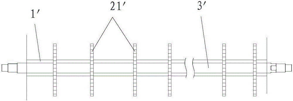
An adjustment method and technology of a slitting machine, applied to the adjustment of the saw blade position of the floor slitting machine, in the field of floor slitting machines, can solve the problems of floor material size error, wear of sleeve 1', cumbersome operation process, etc., and achieve Guaranteed accuracy, reduced horizontal length, and precise position positioning

Inactive Publication Date: 2016-08-17
江苏豪凯机械有限公司
View PDF8 Cites 5 Cited by
  • Summary
  • Abstract
  • Description
  • Claims
  • Application Information

AI Technical Summary

Problems solved by technology

Working for a long time often causes the sleeve 1' to be worn, so that the size of the floor section will be in error and the accuracy will be affected. In addition, to adapt to the cutting of different specifications of the section, it is necessary to fix all the saw blades 21' fixed on the main shaft 3'. Remove it, then reassemble it with the sleeve 1' of different lengths and install it on the main shaft 3', the operation process is very cumbersome and the work efficiency is low

Method used


Image

  • Adjusting method for positions of saw blades of floor dividing and cutting machine and floor dividing and cutting machine
  • Adjusting method for positions of saw blades of floor dividing and cutting machine and floor dividing and cutting machine
  • Adjusting method for positions of saw blades of floor dividing and cutting machine and floor dividing and cutting machine

Examples


Embodiment Construction

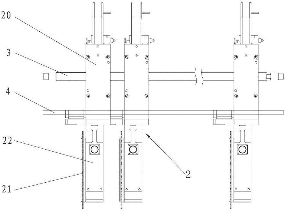
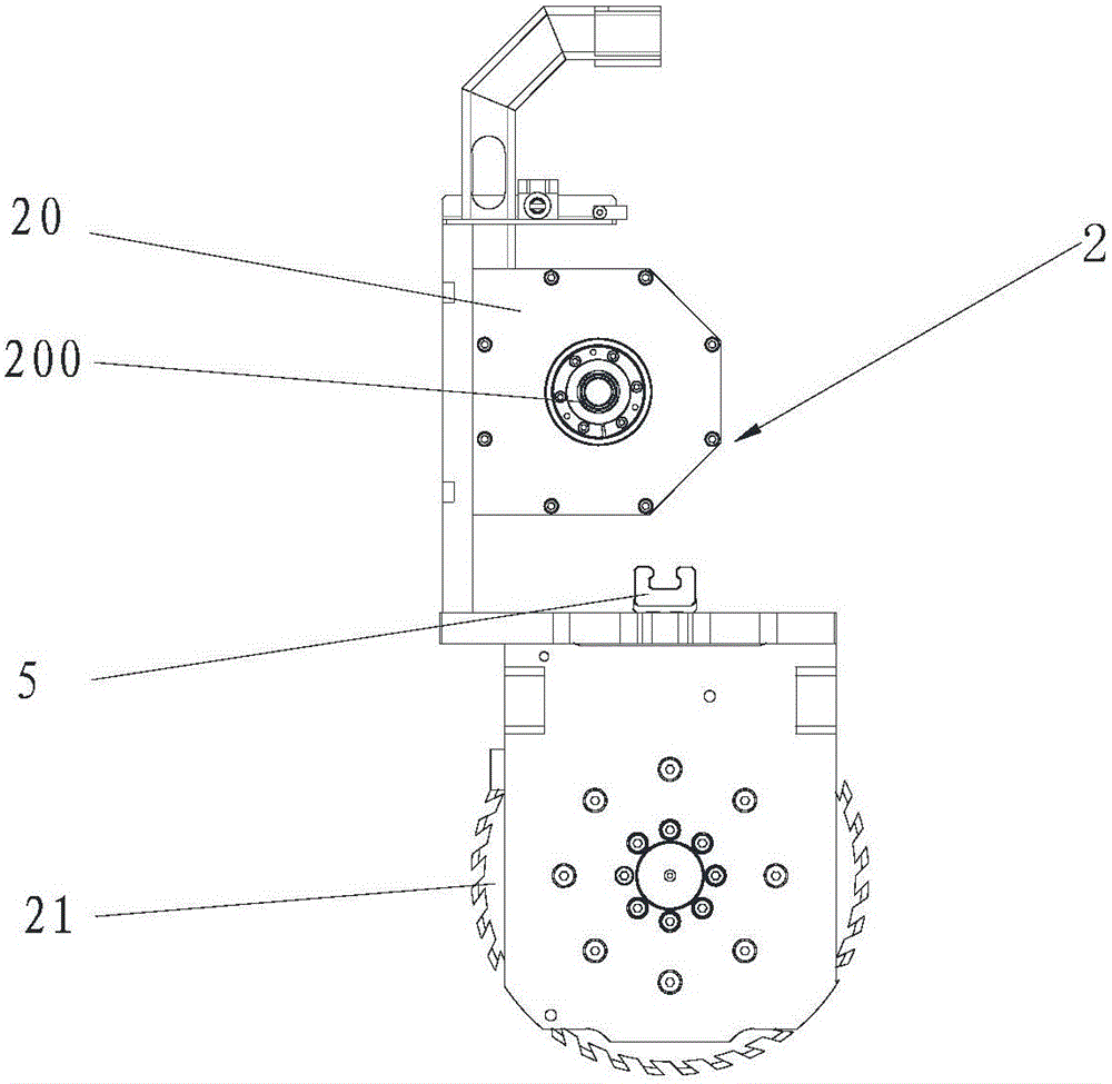
[0022] A method for adjusting the position of a saw blade of a floor slitting machine and the floor slitting machine are suitable for cutting floor boards into sections of various specifications.

[0023] In order to make the purpose, technical solutions and advantages of the embodiments of the present invention clearer, the technical solutions in the embodiments of the present invention will be clearly and completely described below in conjunction with the drawings in the embodiments of the present invention. Obviously, the described embodiments It is a part of embodiments of the present invention, but not all embodiments. Based on the embodiments of the present invention, all other embodiments obtained by persons of ordinary skill in the art without making creative efforts belong to the protection scope of the present invention.

[0024] Compared with the adjustment method of the prior art, the method for adjusting the position of the saw blade of the floor slitter according...


PUM


Abstract

The invention discloses an adjusting method for positions of saw blades of a floor dividing and cutting machine. The adjusting method is characterized by comprising specific steps that firstly, each saw blade is mounted on an independent working motor to manufacture an independent cutting head, a stepping motor is arranged on each cutting head, and hollow rotating shafts of all the stepping motors are spirally and fixedly arranged on a lead screw of the dividing and cutting machine in a sleeving manner; and secondly, the fact that a single stepping motor is driven to move on the lead screw is used for achieving adjustment of the positions of the cutting heads. The invention further discloses the floor dividing and cutting machine. The floor dividing and cutting machine is characterized by comprising the fixedly-arranged lead screw and the cutting heads, each cutting head comprises the corresponding saw blade, the corresponding working motor for driving the saw blade to rotate and the corresponding stepping motor, the stepping motors are provided with the hollow rotating shafts, and the hollow rotating shafts are spirally arranged on the lead screw in the sleeving manner. Adjustment of the saw blade positions is convenient to operate, the saw blade positions are accurate in positioning, and the divided and cut materials are high in size precision.

Description

technical field [0001] The invention relates to the field of woodworking machinery, in particular to a method for adjusting the position of a saw blade of a floor slitter and the floor slitter. Background technique [0002] The floor slitting machine uses the rotating saw blade 21' to cut the boards that move relatively linearly. In order to increase the cutting efficiency, it is often necessary to cut multiple sections of the same specification or different specifications from one board at the same time. This requires adjusting the adjacent The distance between the saw blades 21' (usually the position of the saw blades 21' is based on the initial point, that is, the distance between the saw blades 21' and the initial point is adjusted). like figure 1 As shown, a plurality of saw blades 21' are fixed in parallel on a main shaft 3', and the working motor drives the main shaft 3' to rotate to drive the saw blades 21' to rotate. In the prior art, the position of the saw blades...

Claims


Application Information

Patent Timeline
Patent Type & Authority Applications(China)
IPC IPC(8): B27B5/075B27B5/34B27B5/29
CPCB27B5/075B27B5/29B27B5/34
Inventor 王凯
Owner 江苏豪凯机械有限公司
Why Eureka
Try Eureka