A fully automatic cement brick cutting machine

A brick cutting machine, fully automatic technology, applied in the field of fully automatic cement brick cutting machine, can solve the problems of cement brick vibration, instability, falling, etc., and achieve the effect of stable cutting process, high cutting efficiency and novel structure

Inactive Publication Date: 2018-02-23
江苏弗林特机电科技有限公司
View PDF7 Cites 0 Cited by
  • Summary
  • Abstract
  • Description
  • Claims
  • Application Information

AI Technical Summary

Problems solved by technology

Cement bricks need to be placed on the cutting machine for cutting after demolding. The existing cement brick cutting machines mainly use chains to transport cement bricks, but the chain transmission process is relatively unstable, and the end of the chain is a circular arc transition. Cement bricks will vibrate or fall from the end of the chain, reducing the yield of cement bricks
Furthermore, existing cement brick cutting machines cannot cut continuously, which will affect the cutting efficiency of cement bricks and is not conducive to the popularization and application of production enterprises.

Method used


Image

  • A fully automatic cement brick cutting machine
  • A fully automatic cement brick cutting machine
  • A fully automatic cement brick cutting machine

Examples


Embodiment Construction

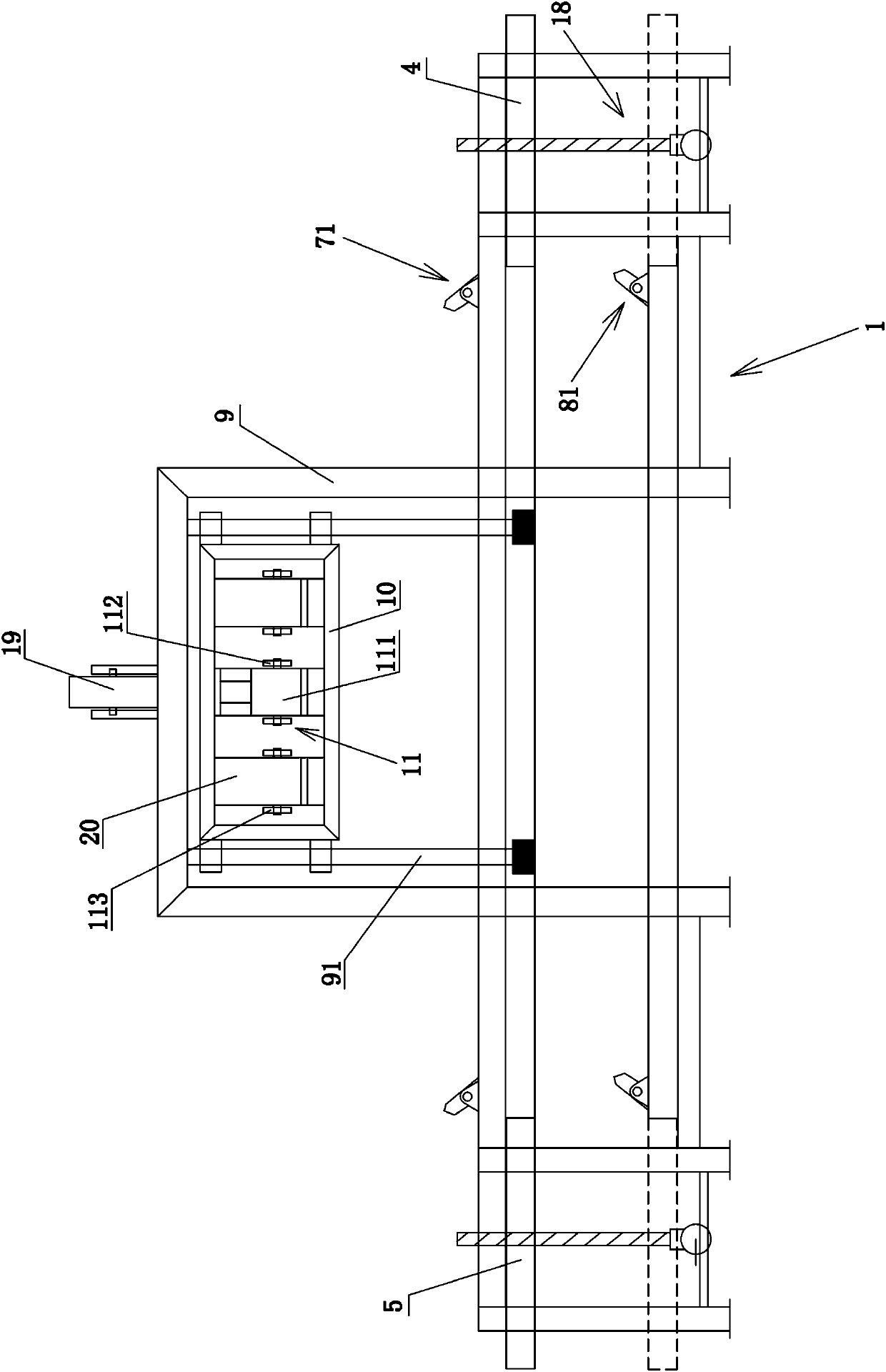
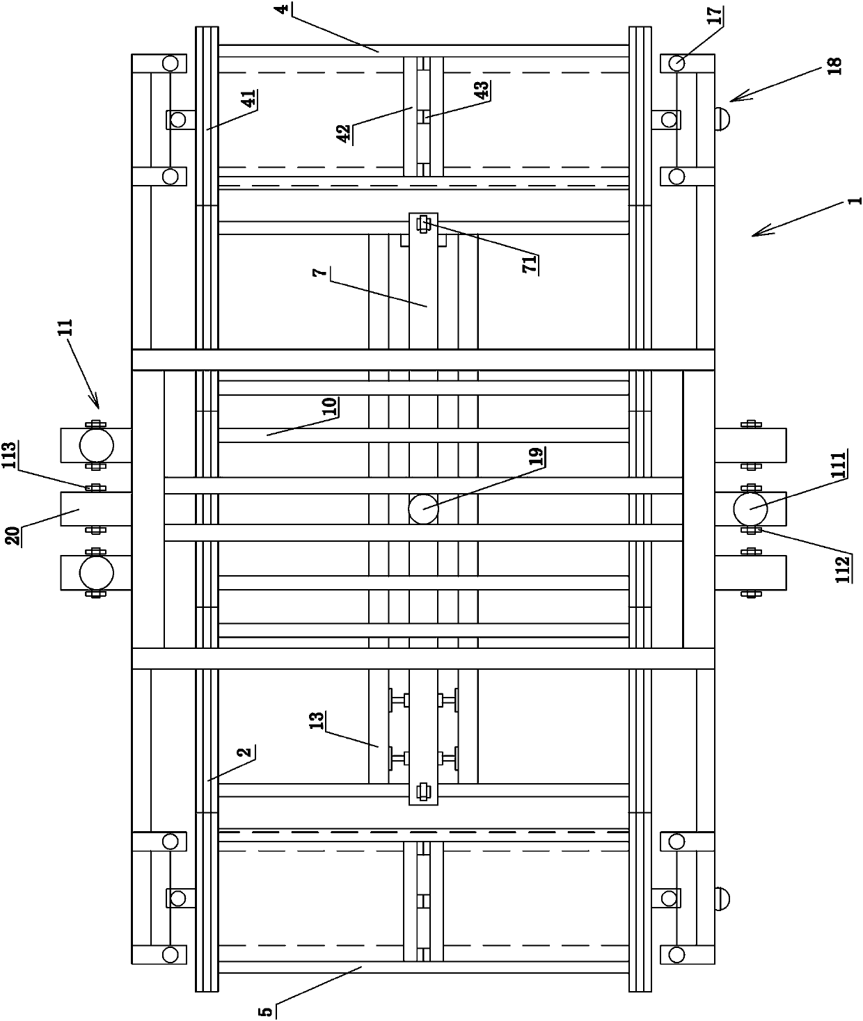
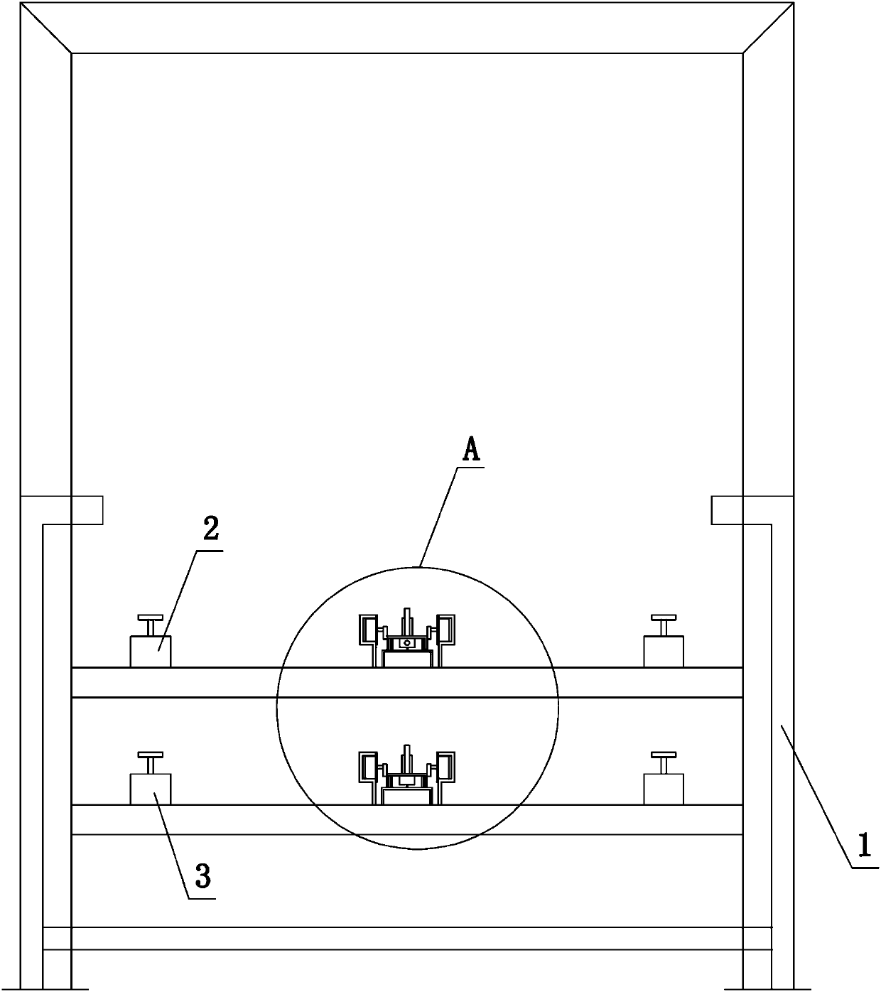
[0024] refer to figure 1 , figure 2 , image 3 , Figure 5 and Figure 6 . A fully automatic cement brick cutting machine comprises a frame 1, on which two upper slide rails 2 arranged at intervals from left to right and two lower rails 3 arranged at intervals from left to right are arranged on the frame 1. The front and rear parts of the frame 1 are respectively provided with a front lifting frame 4 and a rear lifting frame 5, and the top surfaces of the front lifting frame 4 and the rear lifting frame 5 are respectively provided with two front slide rails 41 and two rear slide rails. (not marked in the figure), the structures of the two front slide rails 41 and the two rear slide rails (not marked in the figure) are the same. After the front lifting frame 4 and the rear lifting frame 5 are raised, the two front slide rails 41 and the two rear slide rails (not shown in the figure) are connected with the two upper slide rails 2 and are flush with each other. After the r...


PUM


Abstract

A full-automatic cement brick cutting machine comprises a machine frame. Two upper sliding rails and two lower sliding rails are arranged on the machine frame. A front lifting frame and a rear lifting frame are arranged on the front part and the rear part of the machine frame respectively. Two front sliding rails and two rear sliding rails are arranged on the top surface of the front lifting frame and the top surface of the rear lifting frame respectively. After the front lifting frame and the rear lifting frame ascend, the two front sliding rails and the two rear sliding rails are correspondingly connected with the two upper sliding rails; after the front lifting frame and the rear lifting frame descend, the two front sliding rails and the two rear sliding rails are correspondingly connected with the two lower sliding rails. A plurality of tackles capable of sliding on the front sliding rails, the upper sliding rails, the rear sliding rails and the lower sliding rails circularly are arranged on the machine frame. An upper sliding rod is arranged between the two upper sliding rails, and a plurality of upper driving pieces capable of rotating are arranged on the top surface of the upper sliding rod at intervals front and back. A lower sliding rod is arranged between the two lower sliding rails, and a plurality of lower driving pieces capable of rotating are arranged on the top surface of the lower sliding rod at intervals front and back. A support is arranged in the middle of the machine frame, a cutting frame capable of ascending and descending is arranged on the support, and a plurality of cutting devices are arranged on the cutting frame.

Description

technical field [0001] The invention relates to the field of cutting equipment, in particular to a fully automatic cement brick cutting machine. Background technique [0002] Cement brick refers to a new type of wall material that uses fly ash, cinder, tailings slag, chemical slag or natural sand, sea mud, etc. as the main raw material, uses cement as the coagulant, and does not undergo high-temperature calcination. Cement bricks need to be placed on the cutting machine for cutting after demolding. The existing cement brick cutting machines mainly use chains to transport cement bricks, but the chain transmission process is relatively unstable, and the end of the chain is a circular arc transition. Cement bricks may vibrate or fall from the end of the chain, thereby reducing the yield of cement bricks. Furthermore, existing cement brick cutters cannot cut continuously, which will affect the cutting efficiency of cement bricks and is unfavorable for popularization and applica...

Claims


Application Information

Patent Timeline
Patent Type & Authority Patents(China)
IPC IPC(8): B28B11/14B28B17/00
CPCB28B11/14B28B17/0036
Inventor 蔡清照
Owner 江苏弗林特机电科技有限公司
Why Eureka
Try Eureka