Self-lubricating floating sandwich channel type electrified railway power transmission system

A power transmission system and self-lubricating technology, which is applied to current collectors, electric vehicles, power rails, etc., to achieve the effects of prolonging service life, avoiding impact phenomena, and ensuring driving safety

Active Publication Date: 2016-08-17
天津益昌电气设备股份有限公司
View PDF5 Cites 1 Cited by
  • Summary
  • Abstract
  • Description
  • Claims
  • Application Information

AI Technical Summary

Problems solved by technology

[0005] In order to solve the problems existing in the rail transit power transmission system, the present i

Method used


Image

  • Self-lubricating floating sandwich channel type electrified railway power transmission system
  • Self-lubricating floating sandwich channel type electrified railway power transmission system
  • Self-lubricating floating sandwich channel type electrified railway power transmission system

Examples


Embodiment Construction

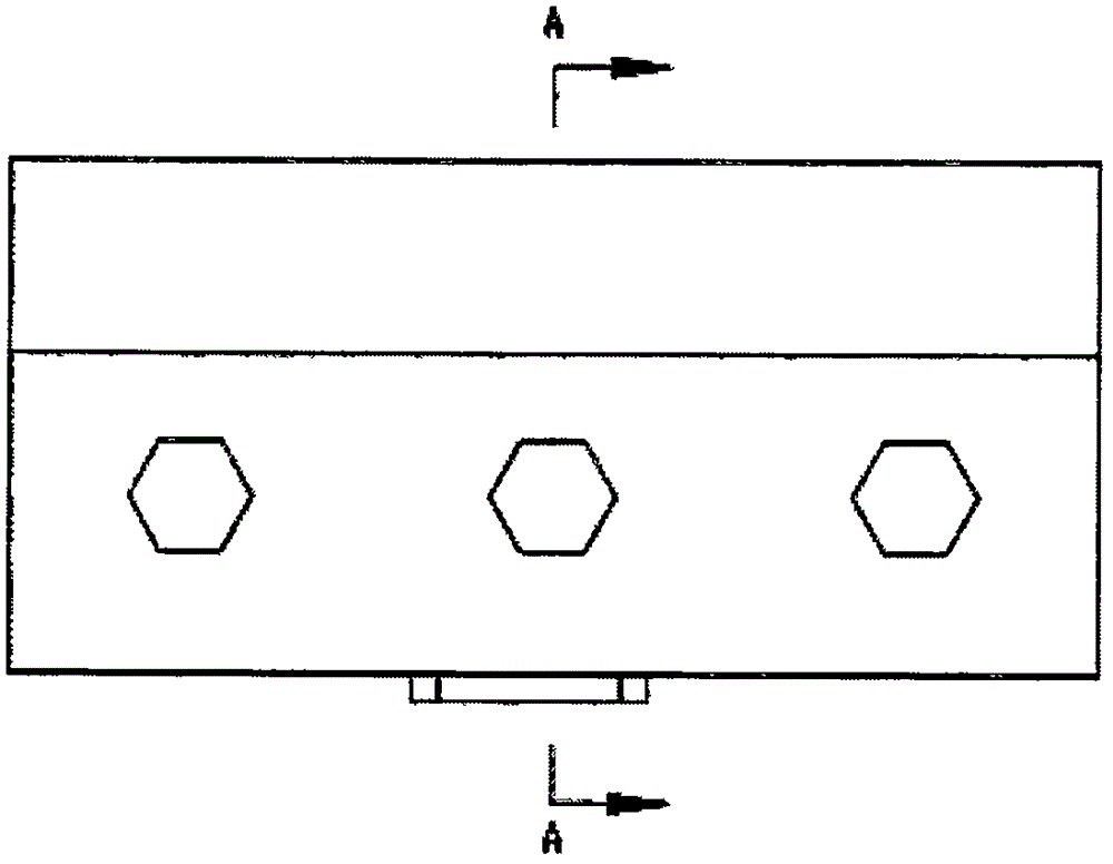
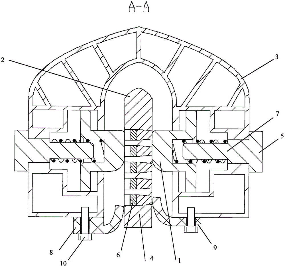
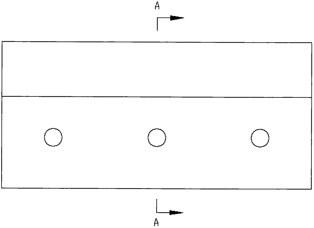
[0028] A self-lubricating floating sandwich channel rail transit power transmission system, such as image 3 and Figure 4 As shown, its three-dimensional support shield 3 is made of insulating material, has a plurality of slotted hole structures in the middle, and has spring fixing holes 11 on its side. The self-lubricating floating channel 1 is made of conductors such as copper and aluminum, and is located One of the slots in cover 3, such as figure 1 and figure 2 As shown, the lower edge 21 of the floating channel is in contact with the three-dimensional support shield 3 slot holes and is supported by it. There is a floating channel spring hole 20 on the side of the self-lubricating floating channel 1. One end of the spring 7 is located in the spring hole 20 of the floating channel, and the other end Withstood against the spring plug 5, the spring plug 5 and the spring fixing hole 11 are threaded or glued or tightly connected and fastened. The self-lubricating conductiv...


PUM


Abstract

The invention discloses a self-lubricating floating sandwich channel type electrified railway power transmission system, and belongs to the technical field of contact current transmission. The system comprises two self-lubricating floating channels, a self-lubricating conducting plate and a three-dimensional supporting protective cover; the self-lubricating conducting plate is located in the three-dimensional supporting protective cover, and therefore the problem that the current-receiving quality of a railway vehicle is influenced by unfavorable natural conditions is avoided; the self-lubricating conducting plate is made of conductors such as copper, aluminum and steel, and therefore the problems of metal-impregnated carbon sliding plate impacting and block falling are avoided; in addition, due to the fact that the back sides of the two self-lubricating floating channels are both supported by springs, the impact phenomenon generated when the self-lubricating conducting plate enters the space between the two self-lubricating floating channels is avoided, the service life of a current collector is prolonged, and the driving safety is guaranteed.

Description

technical field [0001] The invention belongs to the technical field of contact current transmission, and in particular relates to a self-lubricating floating sandwich channel type electrified railway power transmission system. Background technique [0002] With the growth of the national economy and the improvement of people's living standards, electrified railway has become the main mode of transportation in today's society, and it has the characteristics of large capacity and fast speed. However, the current technology of rail transit power transmission system is outdated, low in efficiency and high in faults, which is far from adapting to the development of modern rail transit and severely restricts the improvement of rail transit capacity and efficiency. [0003] Whether it is catenary power supply or catenary rail power supply, a carbon slide will protrude from the rail vehicle to contact the catenary line of the catenary system, or contact the current receiving surface...

Claims


Application Information

Patent Timeline
IPC IPC(8): B60L5/00B60M1/30
CPCB60L5/00B60M1/30
Inventor 李相泉
Owner 天津益昌电气设备股份有限公司
Why Eureka
Try Eureka