
Mechanical arm

A technology of mechanical arms and moving arms, applied in the direction of manipulators, conveyors, conveyor objects, etc., can solve the problems of poor static elimination ability, abnormal vacuum, difficult selection of suction nozzles on the arm, etc., to achieve easy suction and eliminate static electricity Effect

Active Publication Date: 2018-03-13
TCL CHINA STAR OPTOELECTRONICS TECH CO LTD
View PDF5 Cites 0 Cited by
  • Summary
  • Abstract
  • Description
  • Claims
  • Application Information

AI Technical Summary

Problems solved by technology

This is likely to cause the following three problems: first, the mechanical arm will lift the panel when absorbing the cushion, and the adhesive force is not enough to completely absorb the panel, which will cause the panel to fall and cause fragments during the movement of the mechanical arm; Second, it is difficult to select the suction nozzle on the arm. When the adhesive force is high, the sticking phenomenon will be intensified. Blowing directly into the panel, poor static elimination

Method used


Image

  • Mechanical arm
  • Mechanical arm
  • Mechanical arm

Examples


Embodiment Construction

[0027] The present invention will be described in detail below in conjunction with the accompanying drawings and embodiments.

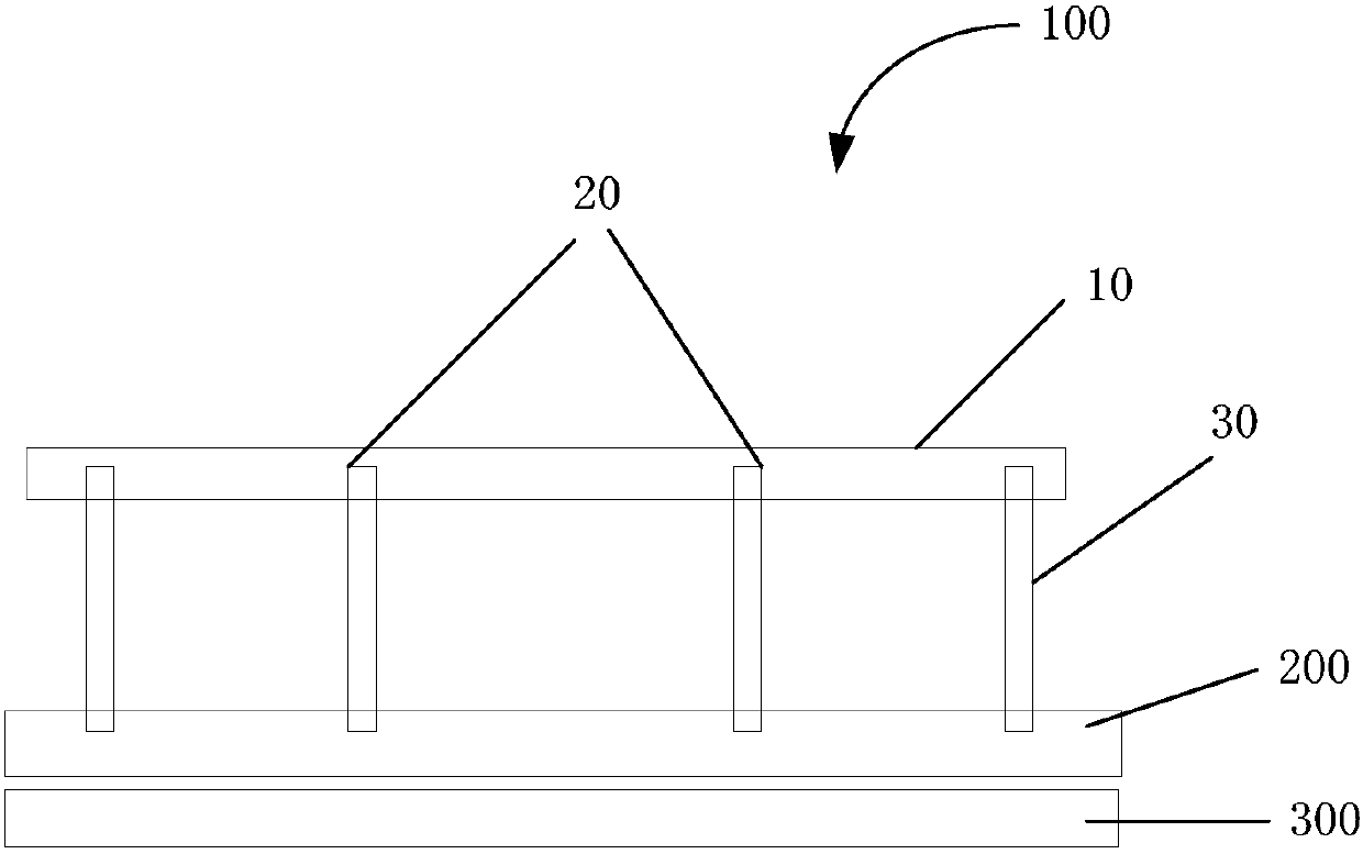
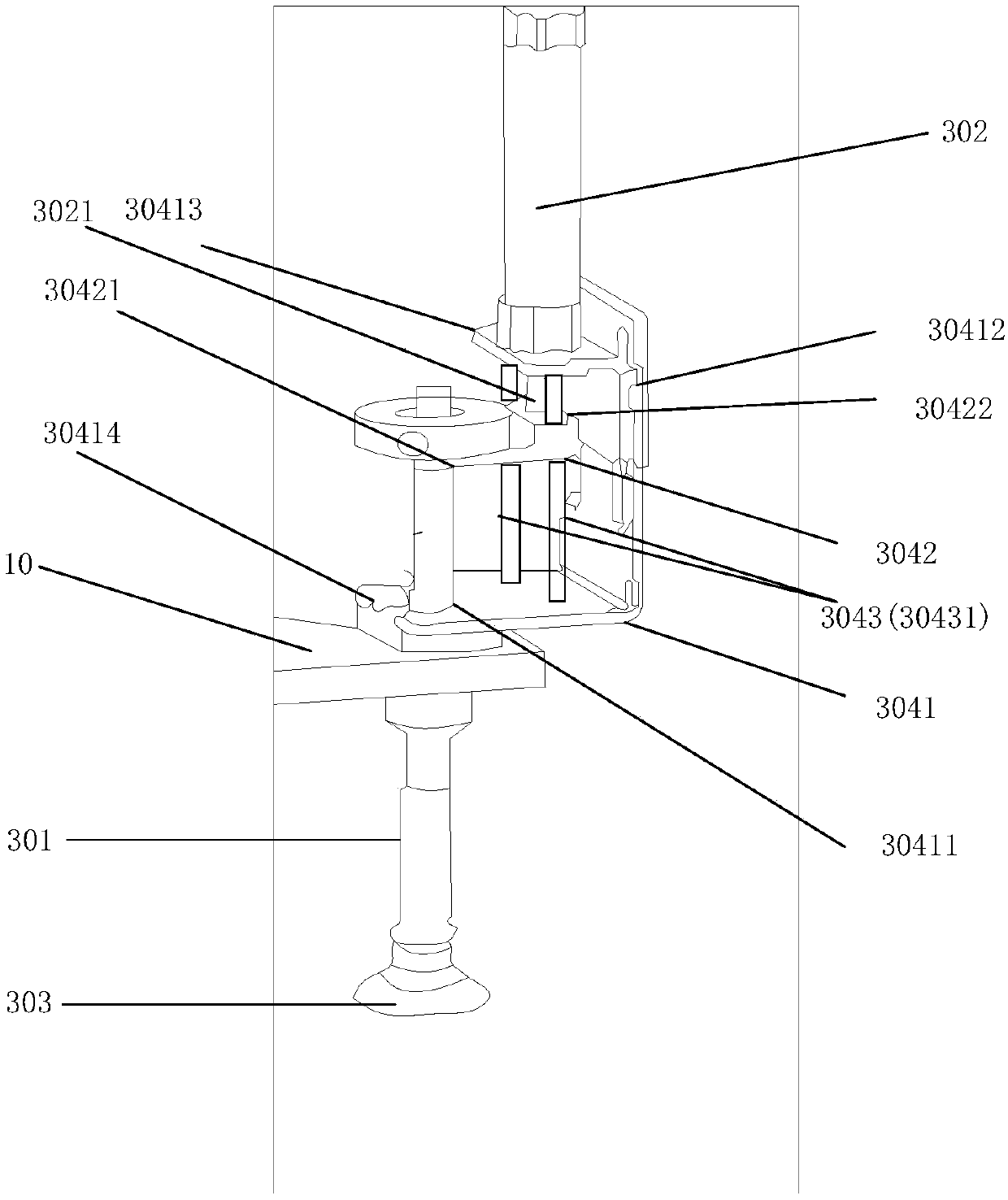
[0028] refer to figure 1 with figure 2 , figure 1 with figure 2 is a structural schematic diagram of an embodiment of the robot arm of the present invention, wherein, figure 1 is a schematic diagram of the robot arm touching the first object and the panel, figure 2 is a schematic diagram of the robotic arm picking up the edge of the first object.

[0029] The robot arm 100 includes: a moving arm 10 , a first type of suction device 20 and a second type of suction device 30 .

[0030] The moving arm 10 is arranged horizontally, and is used for moving horizontally or vertically to move away from or approach the first object 200 to be adsorbed, and the first object 200 is in close contact with the panel 300 .

[0031] In practical applications, the mobile arm 10 may be a flat plate arranged horizontally, or a frame arranged horizontally, or other...


PUM


Abstract

The invention discloses a mechanical arm. The mechanical arm comprises a moving arm, a first adsorption device and a second adsorption device. The moving arm is horizontally arranged and moves in the horizontal direction or vertical direction to be away from or close to a first object to be adsorbed, and the first object is in tight contact with a panel; the first adsorption device is fixedly arranged on the moving arm and used for adsorbing the non-edge of the first object in contact with the first adsorption device under the vacuum effect; and the second adsorption device is movably arranged on the edge position of the moving arm, can vertically move in the vertical direction, is used for adsorbing the edge of the first object in contact with the second adsorption device under the vacuum effect, and can vertically move to enable the edge of the first object to be adsorbed, so that the edge of the first object is separated from the panel. Through the manner, adhesive force between the first object and the panel can be reduced, and it is ensured that the first object and the panel are separated very easily.

Description

technical field [0001] The invention relates to a mechanical arm. Background technique [0002] Liquid crystal panels need to be packaged and transported in batches during the production process. During this process, a soft cushion is used between the panels to isolate the two panels. The panel needs to be separated from the cushion during the unpacking process. [0003] Take the unpacking machine in the module factory as an example. The unpacking machine uses two robotic arms to separate the packaged panels from the cushions, and then inserts the panels into the clips one by one, and puts them into the main line of production. Strong adhesion will be generated between the panel and the cushion due to static electricity and negative pressure. This is likely to cause the following three problems: first, the mechanical arm will lift the panel when absorbing the cushion, and the adhesive force is not enough to completely absorb the panel, which will cause the panel to fall an...

Claims


Application Information

Patent Timeline
Patent Type & Authority Patents(China)
IPC IPC(8): B65G47/91B65B69/00B25J15/06
CPCB25J15/0616B65B69/00B65G47/918B65G2201/022
Inventor 黄安周均王晶邓忠国赵艳彬程威
Owner TCL CHINA STAR OPTOELECTRONICS TECH CO LTD
Learn More