
Grouting reinforcing large-deformation anchor bolt and method using grouting reinforcing large-deformation anchor bolt to reinforce rock body

A technology of grouting reinforcement and large deformation, which is used in the installation of bolts, earth-moving drilling, mining equipment, etc., can solve the problem of high material cost of large deformation bolts, unsuitable for large-area use, failure of bolt support, etc. problems, to achieve the effect of improving service life, simple structure, and reinforcement stability

Inactive Publication Date: 2016-08-17
GUIZHOU UNIV
View PDF10 Cites 9 Cited by
  • Summary
  • Abstract
  • Description
  • Claims
  • Application Information

AI Technical Summary

Problems solved by technology

[0006] The purpose of the present invention is to provide a grouting method for strengthening large deformation bolts and using it to strengthen rock mass, so as to solve the problem that the existing bolts are easily damaged due to the large tensile stress in the deep roadway, and the compression The material cost of the large deformation bolt is high, and it is not suitable for large-scale use. Although the existing large deformation bolt has played a certain role, the breakage of the bolt is still the most important factor leading to the failure of the final support.

Method used


Image

  • Grouting reinforcing large-deformation anchor bolt and method using grouting reinforcing large-deformation anchor bolt to reinforce rock body
  • Grouting reinforcing large-deformation anchor bolt and method using grouting reinforcing large-deformation anchor bolt to reinforce rock body
  • Grouting reinforcing large-deformation anchor bolt and method using grouting reinforcing large-deformation anchor bolt to reinforce rock body

Examples


Embodiment

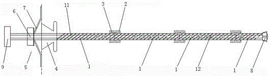
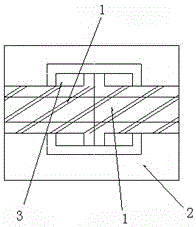
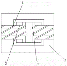
[0021] Reference figure 1 , 2 And 3, this embodiment provides a grouting-reinforced large-deformation anchor rod. The anchor rod is formed by successively butting four sections of rod body 1 along the length direction through casing 2 (the rod bodies 1 are coaxially arranged), and one end of the anchor rod An anchor head 8 is provided, and a grout plug 9 is provided at the other end. A grout hole 11 is opened in the rod body 1 in the anchor rod along its length. The grout holes 11 of two adjacent sections of the rod body 1 are connected, and the side of the rod body 1 The wall is provided with a slurry outlet hole 12 communicating with the slurry inlet hole 11. The opposite ends of the two adjacent sections of the rod body 1 are slidably arranged in the casing 2, and the ends of the two sections of rod body 1 and the casing 2 There is a damping part 3 used to hinder the sliding of the rod 1 toward the outside of the sleeve 2 between the rods. The damping part 3 is the damping ma...


PUM


Abstract

The invention provides a grouting reinforcing large-deformation anchor bolt and a method using the grouting reinforcing large-deformation anchor bolt to reinforce a rock body. The grouting reinforcing large-deformation anchor bolt is formed by sequentially butting at least two bolt bodies by a sheath pipe along the length direction; the two opposite ends of the two adjacent bolt bodies are respectively and glidingly arranged in the sleeve pipe; damping parts are respectively arranged between the ends of the two bolt bodies and the sleeve pipe, and are used for preventing the bolt bodies from sliding to the exterior direction of the sleeve pipe; a grouting stop plug is sheathed at the outer side of one end of each anchor bolt, and is used for preventing the grout from flowing out of an anchor bolt fixing hole; a grouting stop plug fixing part is pressed at the outer side of each grouting stop plug. The grouting reinforcing large-deformation anchor bolt is used for solving the problems that the existing anchor bolt is easily damaged due to larger pull stress in the deep tunnels, the material cost of the yield large-deformation anchor bolt is high, and the anchor bolt is not suitable for large-area use; although a certain function of the existing yield large-deformation anchor bolt is realized, the pull breaking of the anchor bolt is still the major factor causing the failure of final support. The grouting reinforcing large-deformation anchor bolt belongs to the field of rock body reinforcing of mines.

Description

Technical field [0001] The invention relates to a grouting reinforcement anchor rod and a reinforcement method, belonging to the field of rock mass reinforcement. Background technique [0002] At present, as the mining depth continues to increase, the surrounding rock pressure also continues to increase. Facing the deep weak rock mass and high ground stress, the currently known bolts are subject to greater tensile stress in the deep roadway and are easily broken. When the rock mass is broken to a high degree, the anchoring effect of the bolt is also prone to failure. Based on such problems, we have made improvements and hoped to play a role in actual production. [0003] However, some existing bolts that allow large deformations also have some problems, mainly as follows: [0004] (1) The cost of large deformable materials is relatively high and is not suitable for large-area use. In the face of common deep mining problems, costs still need to be reduced; [0005] (2) The design is ...

Claims


Application Information

Patent Timeline
IPC IPC(8): E21D21/00E21D20/02
CPCE21D21/0033E21D20/02E21D21/0046E21D21/0093
Inventor 左宇军于美鲁曹俊才曲闯何晨宏张凯董启龙
Owner GUIZHOU UNIV
Learn More