Cantilever angle adjusting mechanism

An angle adjustment and cantilever technology, applied in supporting machines, mechanical equipment, machines/supports, etc., can solve the problems of small weighing range, limited cylinder stroke, and high production cost, and achieve a wide range of adjustment load-bearing, large adjustment angle, The effect of low production cost

Inactive Publication Date: 2016-08-17
KUNSHAN HONGJIE ELECTRONICS CO LTD
View PDF7 Cites 4 Cited by
  • Summary
  • Abstract
  • Description
  • Claims
  • Application Information

AI Technical Summary

Problems solved by technology

[0002] At present, most audio-visual equipment is installed on the wall through brackets to save indoor space. At the same time, it can also prevent audio-visual equipment from being tilted and broken by external force. At present, there are cantilever brackets, which are convenient for adjusting the distance between audio-visual equipment and the wall. At the same time, it is also convenient to adjust the height of the audio-visual equipment. The height adjustment of the cantilever bracket to the audio-visual equipment is mainly adjusted by adjusting the tilt angle of the cantilever. The long strip hole or the arc hole is matched, and the bolt is passed through the round hole, the long strip hole or the running hole to connect the base with the cantilever, and the cantilever is realized by adjusting the relative position of the round hole and the long strip hole or the arc hole. For the adjustment of the angle, someone needs to lift the audio-visual equipment to avoid the audio-visual equipment from falling and being damaged suddenly under the action of gravity. Then another worker adjusts the inclination angle by selecting the bolt and then re-tightens the bolt. This kind of cantilever inclination angle adjustment mechanism adjusts Trouble, it can’t be done by one person, the audio-visual equipment can’t stay freely at any position, it needs to be adjusted by the staff before it can be realized, and because it is realized by friction, the connecting parts are prone to wear and tear after long-term use, causing the adjustment function to fail; there is another This cantilever tilting angle adjustment method is realized by the support of the cylinder (gas spring). Although this structure can realize the free stop function of the audio-visual equipment, the cylinder is prone to air leakage, the service life is short, and the stroke of the cylinder is limited. Adjusting the angle is called Small weight range, high production cost

Method used


Image

  • Cantilever angle adjusting mechanism
  • Cantilever angle adjusting mechanism
  • Cantilever angle adjusting mechanism

Examples


Embodiment

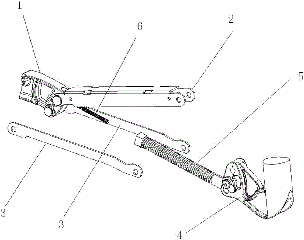
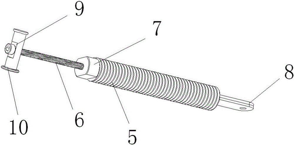
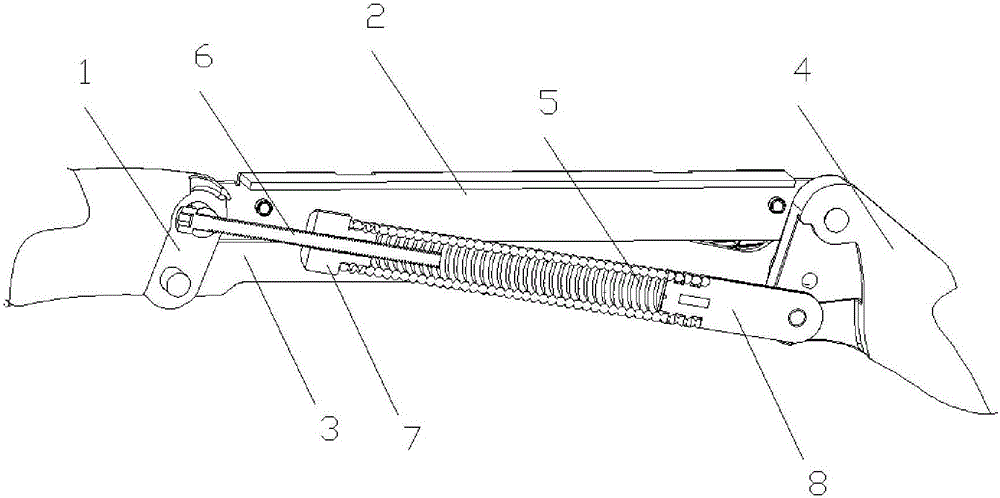
[0013] Embodiment: A cantilever angle adjustment mechanism, including a support 1, first and second cantilever connecting rods 2, 3, a connecting piece 4, an elastic body 5, and an adjustment shaft 6, the support 1, the first and second cantilever The connecting rods 2, 3 and the connecting piece 4 are hinged to form a parallel four-bar linkage mechanism, in which the first and second cantilever connecting rods 2, 3 are arranged in parallel, and the adjusting shaft 6 is coaxially connected with the elastic body 5 to form an angle adjusting mechanism. The two ends of the angle adjustment mechanism are respectively hinged with the two diagonal hinge shafts 10 of the above-mentioned parallel four-bar linkage mechanism, and the length of the adjustment shaft 6 can be adjusted.

[0014] When in use, install the equipment that requires angle adjustment on the connecting piece 4, and the angle adjustment mechanism composed of the support 1, the first and second cantilever links 2, 3, ...


PUM


Abstract

The invention discloses a cantilever angle adjustment mechanism, which comprises a support, a first and a second cantilever connecting rod, a connecting piece, an elastic body, and an adjusting shaft. The support, the first and second cantilever connecting rods and the connecting piece are hinged to form A parallel four-bar linkage mechanism, in which the first and second cantilever linkages are arranged in parallel, and the adjustment shaft is coaxially connected with the elastic body to form an angle adjustment mechanism. Two diagonal hinge shafts are hinged, the length of the adjustment shaft can be adjusted, the invention can achieve the function of free stop, and the adjustment angle is large, the adjustment load-bearing range is wide, and the adjustment mechanism is simple in structure, low in production cost, and long-term It is not easy to fail when used, and has good stability.

Description

technical field [0001] The invention relates to a cantilever bracket for audio-visual products, in particular to a cantilever angle adjustment mechanism. Background technique [0002] At present, most audio-visual equipment is installed on the wall through brackets to save indoor space. At the same time, it can also prevent audio-visual equipment from being tilted and broken by external force. At present, there are cantilever brackets, which are convenient for adjusting the distance between audio-visual equipment and the wall. At the same time, it is also convenient to adjust the height of the audio-visual equipment. The height adjustment of the cantilever bracket to the audio-visual equipment is mainly adjusted by adjusting the tilt angle of the cantilever. The long strip hole or the arc hole is matched, and the bolt is passed through the round hole, the long strip hole or the running hole to connect the base with the cantilever, and the cantilever is realized by adjusting ...

Claims


Application Information

Patent Timeline
Patent Type & Authority Applications(China)
IPC IPC(8): F16M13/02F16M11/10
CPCF16M13/022F16M11/10F16M2200/041
Inventor 常晓杰
Owner KUNSHAN HONGJIE ELECTRONICS CO LTD
Why Eureka
Try Eureka