
Heat pump type air-conditioning heat exchanger with heat exchange working medium flow direction and flow path number in synchronous change

A technology of synchronously changing and heat-exchanging working medium, which is applied in household heating, heating methods, household heating, etc., can solve the problems of long flow path, reduced heat exchange performance, and high refrigerant flow rate, etc. reliability effect

Inactive Publication Date: 2016-08-17
SHANGHAI JIAO TONG UNIV +1
View PDF7 Cites 7 Cited by
  • Summary
  • Abstract
  • Description
  • Claims
  • Application Information

AI Technical Summary

Problems solved by technology

When this technology is applied to the condenser, the refrigerant first divides into two branches and flows into the heat exchanger, and then merges into one flow path to flow out of the heat exchanger; the number of heat exchange tubes in the combined flow path accounts for One-third, the flow path is long and the refrigerant flow rate is high, resulting in a sharp increase in the pressure drop of the two-phase refrigerant in the combined flow path, which reduces the heat transfer performance; at the same time, the three electronic expansion valves in this technology require complex electrical Signal control, high cost, unstable control

Method used


Image

  • Heat pump type air-conditioning heat exchanger with heat exchange working medium flow direction and flow path number in synchronous change

Examples


Embodiment 1

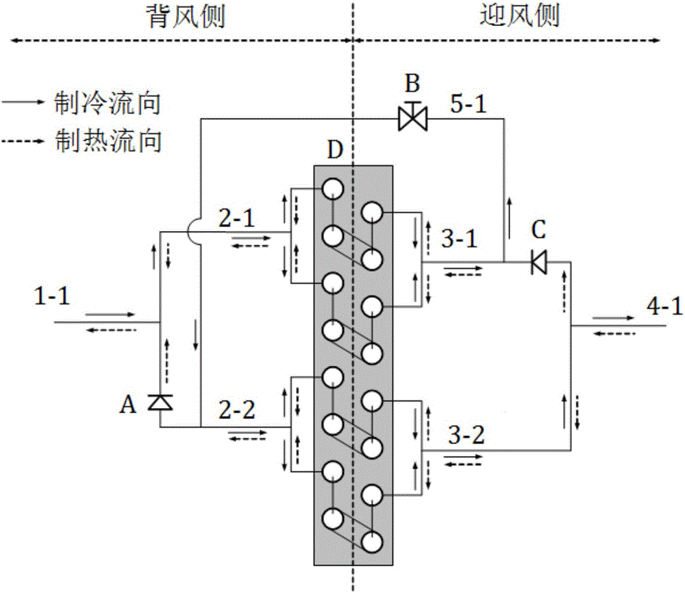
[0015] Such as figure 1 As shown, the present embodiment includes: main pipe 1-1 on the leeward side, first branch pipe 2-1 on the leeward side, second branch pipe 2-2 on the leeward side, main pipe 4-1 on the windward side, first branch pipe 3-1 on the windward side, The second branch pipe 3-2 on the side and the heat exchanger D, wherein: the heat exchanger D is provided with 2n flow paths, the main pipe 1-1 on the leeward side is connected with the first branch pipe 2-1 on the leeward side and the second branch pipe 2-1 on the leeward side respectively. 2 connected, the main pipe 4-1 on the windward side is connected to the first branch pipe 3-1 on the windward side and the second branch pipe 3-2 on the windward side respectively, and the first branch pipe 2-1 on the leeward side and the first branch pipe 3-1 on the windward side are set correspondingly and They are respectively connected to the leeward side port and the windward side port of the n flow paths in the heat ex...


PUM


Abstract

The invention discloses a heat pump type air-conditioning heat exchanger with a heat exchange working medium flow direction and a flow path number in synchronous change. The heat pump type air-conditioning heat exchanger comprises a heat exchanger with 2n flow paths, first and second branch pipes at a leeward side, first and second branch pipes at a windward side, a header pipe at the leeward side and a header pipe at the windward side, wherein the header pipe at the leeward side is separately connected with the first branch pipe and the second branch pipe at the leeward side; the header pipe at the windward side is separately connected with the first branch pipe and the second branch pipe at the windward side; the branch pipes at the leeward side and the branch pipes the windward side are correspondingly arranged, and are separately connected with end openings at the leeward side and the windward side of the n flow paths in the heat exchanger; the second branch pipe at the leeward side and the first branch pipe at the windward side are provided with one-way valves; the inlet end of the one-way valve of the second branch pipe at the leeward side and the outlet end of the one-way valve of the first branch pipe at the windward side are connected through a pipeline to form a refrigerating branch pipe; and the refrigerating branch pipe is provided with an electronic valve. The number of the flow paths of the heat exchanger is changed with the switching of a refrigerating working condition and a heating working condition while the flow direction of the heat exchange working medium is changed with the switching of the working condition, so that the performances of an air conditioner are optimal.

Description

technical field [0001] The invention relates to a technology in the field of air conditioning, in particular to a heat pump type air conditioner heat exchanger in which the flow direction of heat exchange working fluid and the number of flow paths change synchronously with the change of working conditions. Background technique [0002] The heat pump air conditioner has two working conditions of cooling and heating. When the working conditions are switched, the heat exchanger in the air conditioner is also switched from "evaporator" to "condenser" and "condenser" to "evaporator". change. Taking the outdoor unit as an example, the outdoor unit acts as a "condenser" under cooling conditions, and switches to an "evaporator" under heating conditions. However, in this technology, the optimal number of flow paths between the evaporator and the condenser is different, so that the performance of the heat exchanger with a fixed number of flow paths cannot be optimized under both cool...

Claims


Application Information

Patent Timeline
Patent Type & Authority Applications(China)
IPC IPC(8): F24F13/30F25B39/00F25B41/06F25B41/31
CPCF24F13/30F25B39/00F25B41/31
Inventor 丁国良吴志刚任滔吴国明王利
Owner SHANGHAI JIAO TONG UNIV
Learn More