
Laser scanning range finder

A laser scanning ranging and laser transmitter technology, which is used in measurement devices, radio wave measurement systems, and electromagnetic wave re-radiation, etc. The overall structure is compact, the effect of reducing volume and noise

Active Publication Date: 2016-08-17
SHANGHAI SLAMTEC
View PDF6 Cites 9 Cited by
  • Summary
  • Abstract
  • Description
  • Claims
  • Application Information

AI Technical Summary

Problems solved by technology

However, most of the existing laser scanning distance measuring devices use slip rings when transmitting signals and electric energy, and the transmission is realized by belt or gear meshing, which has disadvantages such as large equipment volume, short service life, and high noise
In addition, the wireless power supply coil in the existing laser scanning distance measuring device often occupies a large volume, which makes the overall device large in size and has strict requirements on the design and installation of the robot.

Method used


Image

  • Laser scanning range finder
  • Laser scanning range finder
  • Laser scanning range finder

Examples


Embodiment Construction

[0024] In order to make the technical content disclosed in this application more detailed and complete, reference may be made to the drawings and the following various specific embodiments of the present invention, and the same symbols in the drawings represent the same or similar components. However, those skilled in the art should understand that the examples provided below are not intended to limit the scope of the present invention. In addition, the drawings are only for schematic illustration and are not drawn according to their original scale.

[0025] The specific implementation manners of various aspects of the present invention will be further described in detail below with reference to the accompanying drawings.

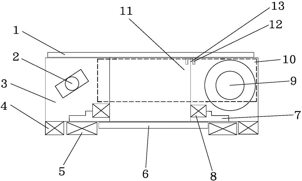
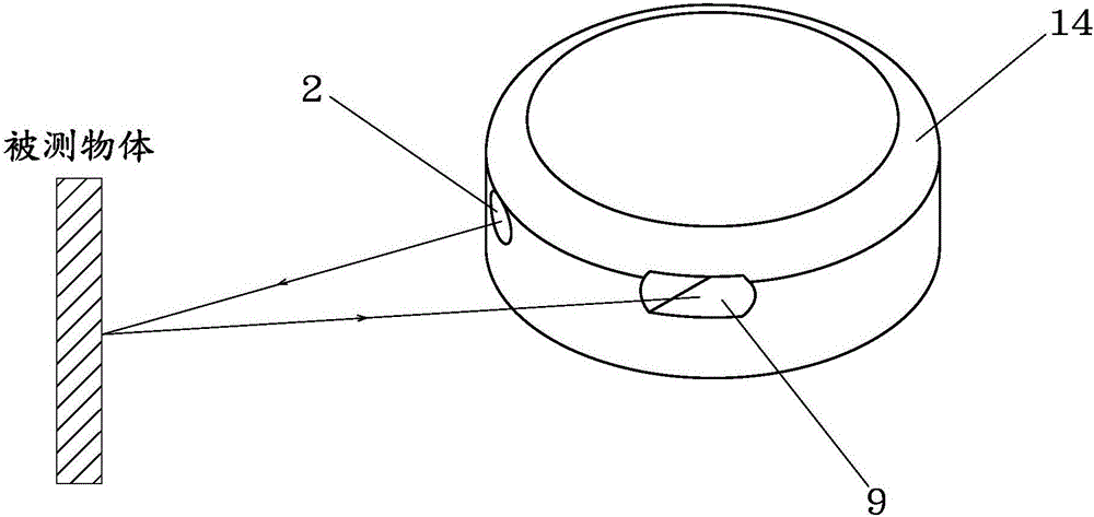
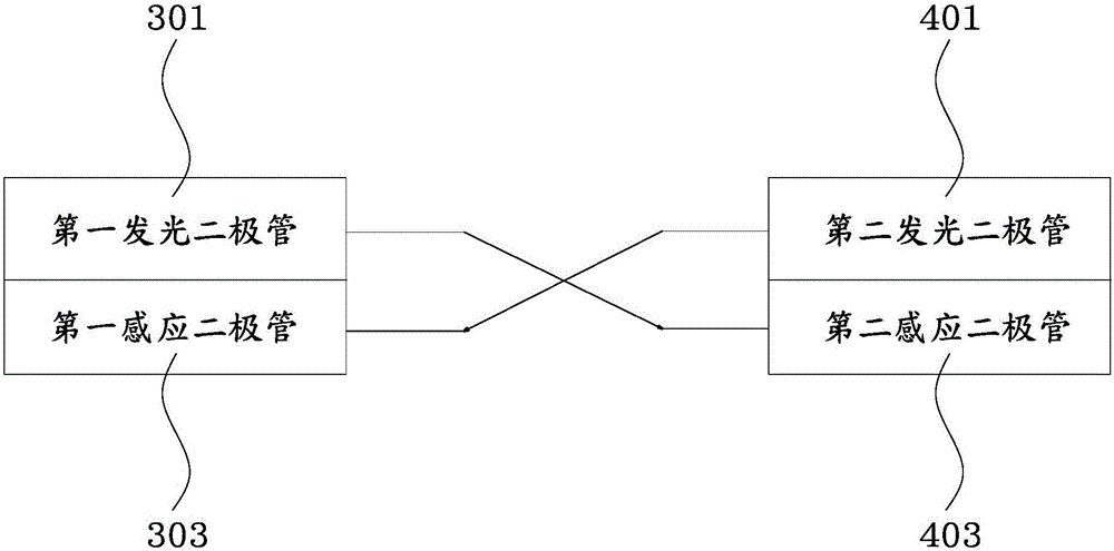
[0026] figure 1 A schematic structural diagram of a laser scanning ranging device according to an embodiment of the present invention is shown. figure 2 shown in figure 1 Schematic diagram of object distance measurement using laser transmitter and laser...


PUM


Abstract

The invention provides a laser scanning range finder. The laser scanning range finder comprises a rotatable rotating structure and a fixed structure incapable of rotating, wherein the rotating structure comprises a receiving plate, a laser transmitter, a skeleton, an outer rotor, a laser receiver and a back plate; the fixed structure comprises a stator coil, a transmitting plate and a transmitting fixed platform. The receiving plate, the laser transmitter, the outer rotor, the laser receiver and the back plate are installed on the skeleton, the stator coil and the transmitting plate are installed on the transmitting fixed platform, and a plane formed by laser transmitted by the laser transmitter and laser received by the laser receiver is parallel to an installing plane. Compared with the prior art, a wireless power supply and full duplex data transmission mode is adopted in the laser scanning range finder, and the defect that the service life is short due to slip ring power supply and communication is overcome. In addition, by means of magnetic medium rotation of electro-magnetic induction, the size and noise are reduced compared with existing belt or gear transmission.

Description

technical field [0001] The invention relates to a robot design technology and a laser scanning technology, in particular to a laser scanning distance measuring device. Background technique [0002] A robot is a machine device that automatically performs work. It can accept human commands, run pre-programmed programs, and act based on principles formulated by artificial intelligence technology. In general, robots are tasked with assisting or replacing humans in tasks such as those in manufacturing, construction or hazardous industries. A mobile robot is a comprehensive system that integrates multiple functions such as environmental perception, dynamic decision-making and planning, behavior control and execution. Explosion, scientific investigation and sampling, etc., so it has great application value in fields such as rescue, scientific research, military and other fields. [0003] In the existing mobile robot applications, for the sake of walking safety, it is often necess...

Claims


Application Information

Patent Timeline
Patent Type & Authority Applications(China)
IPC IPC(8): G01S17/08G01S7/481
CPCG01S7/481G01S17/08
Inventor 徐磁汪迎春刘义春陈士凯李宇翔林凌黄珏珅
Owner SHANGHAI SLAMTEC
Learn More