Floating ball type water level switch

A water level switch and float type technology, applied in the field of float type water level switches, can solve the problems of high cost, complicated reed switch procedures, long cycle, etc., and achieve the effects of simple and convenient installation, shortened cycle, and simplified manufacturing process.

Inactive Publication Date: 2016-08-17
SHANGHAI HOPPY ELECTRONICS ELECTRIC APPLIANCE +2
View PDF3 Cites 1 Cited by
  • Summary
  • Abstract
  • Description
  • Claims
  • Application Information

AI Technical Summary

Problems solved by technology

[0004] The purpose of the present invention is to provide a floating ball water level switch, which solves the disadvantages of using glue to fix the reed switch in the past structure, which has a complicated process, a long cycle, oven drying, and relatively high cost.

Method used


Image

  • Floating ball type water level switch
  • Floating ball type water level switch
  • Floating ball type water level switch

Examples


Embodiment Construction

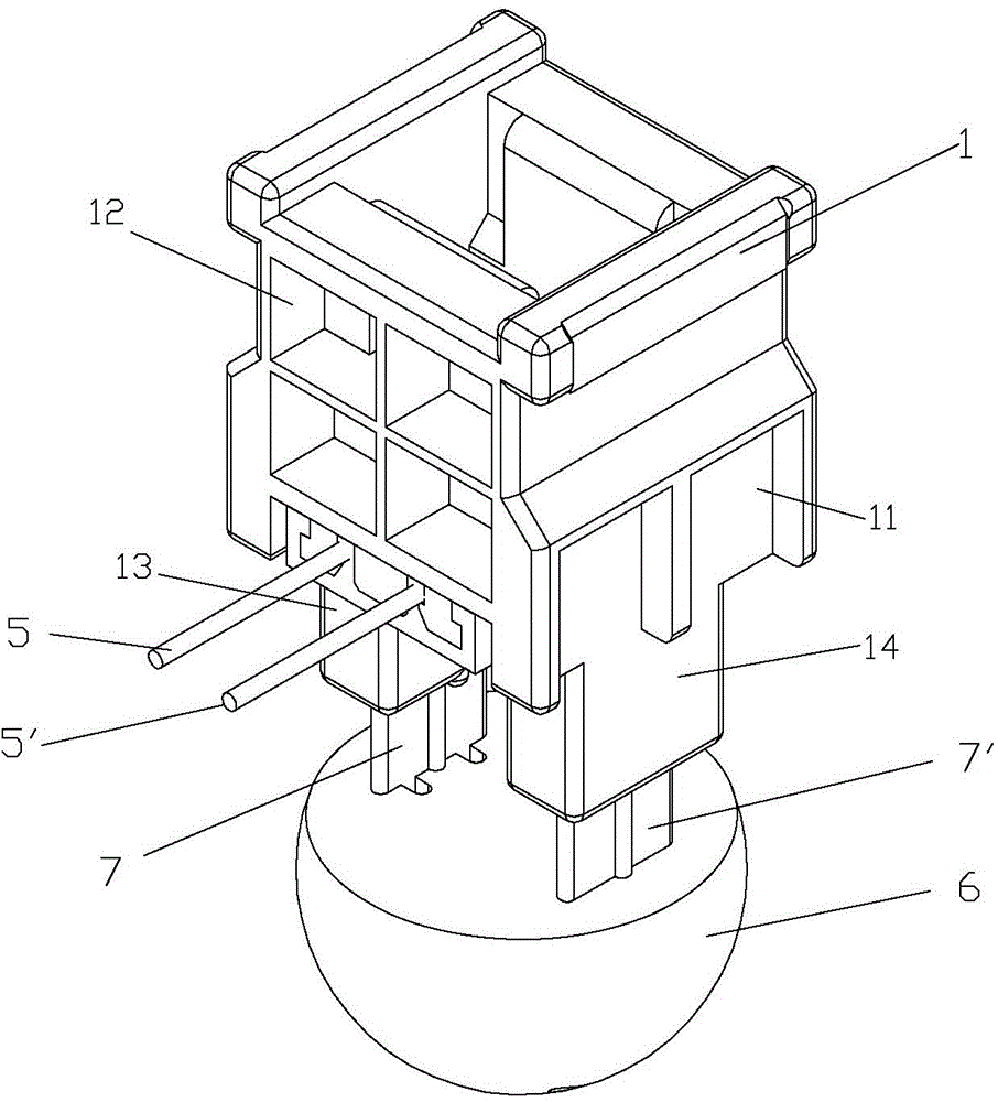
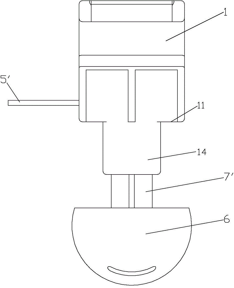
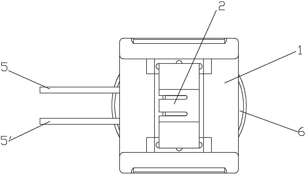
[0021] see Figure 1 to Figure 7 , a kind of floating ball type water level switch of the present invention, comprises, fixed base 1, and it comprises, base plate 11 and frame structure 12 on it, base plate 11 upper end face center is provided with magnet 2, each side of base plate 11 lower end face is vertically arranged A conduit 13, 14; a magnetic reed switch 3, the two ends of which are connected to two lead wires 5, 5' through crimp terminals 4, 4'; a floating ball 6, on which two floating brackets 7, 7' are arranged, and two floating brackets 7 The upper part of , 7 is inserted in the conduits 13, 14 on both sides of the lower end surface of the fixed base 1 bottom plate 11; The conduits 13 and 14 are snap-connected; the middle part of the lower end surface of the bottom plate 11 of the fixed base 1 is provided with an accommodating groove 111, and the reed switch 3 and the crimping terminals 4 and 4' connecting both ends and the two lead wires 5, 5' are embedded in the...


PUM


Abstract

The invention relates to a floating ball type water level switch. The floating ball type water level switch comprises a fixing base, a magnetic reed switch and a floating ball; the fixing base includes a bottom plate and a frame structure on the bottom plate; the center of the upper end surface of the bottom plate is provided with magnets; two sides of the lower end surface of the bottom plate are respectively provided with a guide tube; two ends of the magnetic reed switch are connected with two lead-out wires through crimping terminals; the floating ball is provided with two floating supports; the upper parts of the two floating supports are inserted into the guide tubes at the two sides of the lower end surface of the bottom plate of the fixing base; the two floating supports on the floating ball are connected with the guide tubes at the lower end surface of the bottom plate of the fixing base through a buckling mode; the center of the lower end surface of the bottom plate of the fixing base is provided with an accommodating groove; the magnetic reed switch, the crimping terminals connected with the two ends of the magnetic reed switch and the two lead-out wires are embedded in the accommodating groove, and secondary plastic injection is carried out, so that an integral structure can be formed, and the magnetic reed switch is located below the magnets; and the two lead-out wires extend out from the front end surface of the bottom plate of the fixing base. According to an existing structure, a reed switch is fixed through glue pouring, and as a result, processing procedures are complex, a cycle is long, and the reed switch must be dried by a baking box, and the detect of relatively high cost will be brought about, while, with the floating ball type water level switch adopted, the above detect can be eliminated.

Description

technical field [0001] The invention relates to a water level switch, in particular to a float type water level switch. Background technique [0002] A sensor made of a reed switch (also known as a reed switch or a reed switch) is one of the simplest sensor structures. The advantages of reed switches (magnetic reed switches) are their small size and light weight, which makes them easy to install and unobtrusive. The operating switch is very small, thus eliminating the need for cumbersome cams or cranks, so there is no metal fatigue associated with metal degradation at all, ensuring virtually unlimited mechanical life. Moreover, it can be installed in an extremely limited space, making it ideal for miniaturized equipment. Reed switches, and suitable magnets, are cheap and readily available. The switching components of the magnetic reed switch are hermetically sealed in an inert gas atmosphere and will never be in contact with the external environment, which greatly reduces...

Claims


Application Information

Patent Timeline
IPC IPC(8): H01H36/02
Inventor 施冉
Owner SHANGHAI HOPPY ELECTRONICS ELECTRIC APPLIANCE
Why Eureka
Try Eureka