Electric car power battery thermal management system

A thermal management system and power battery technology, applied in secondary batteries, circuits, electrical components, etc., can solve the problems of reduced service life of power batteries, uneven heating, battery power consumption, etc., to reduce electrical power, reduce the number of components, simple structure

Inactive Publication Date: 2016-08-17
上海松芝酷能汽车技术有限公司
View PDF7 Cites 34 Cited by
  • Summary
  • Abstract
  • Description
  • Claims
  • Application Information

AI Technical Summary

Problems solved by technology

Its disadvantages are: (1) Electric PTC heating consumes high energy consumption, which consumes power battery power, resulting in shortened mileage of electric vehicles; (2) cooling fan cooling radiator lacks the ability to quickly cool down, and the cooling range is limited, resulting in high heat of the power battery. The temperature is not effectively cooled and it is outside the optimum working temperature zone; resulting in a reduction in the service life of the power battery; (3) the risk of thermal runaway of the battery cannot be eliminated
However, its structure is complex and the system reliability is poor
In addition, the electric vehicle thermal management system lacks the function of heating up the battery, which makes the power battery easily lose its function in an extremely low temperature environment
[0006] Chinese patent CN102255115B discloses the technology of "using fan forced convection to cool and heat the battery". Although it has a simple structure, its disadvantages are: it belongs to passive thermal management, and the cooling effect is not ideal; in addition, its battery heating adopts the form of electric PTC , not only consumes battery power, but also heats unevenly, posing safety hazards

Method used


Image

  • Electric car power battery thermal management system
  • Electric car power battery thermal management system
  • Electric car power battery thermal management system

Examples


Embodiment Construction

[0038] A specific implementation of the electric vehicle power battery thermal management system of the present invention will be further described below in conjunction with the accompanying drawings, but it should be pointed out that the implementation of the present invention is not limited to the following implementation.

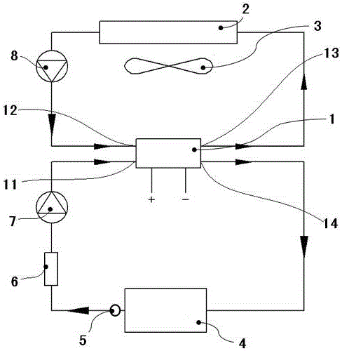
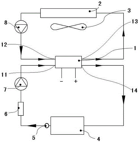
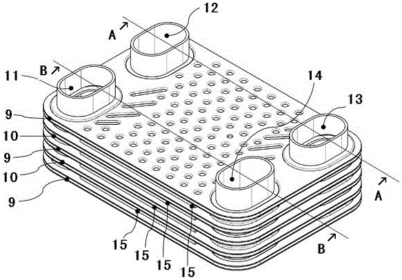
[0039] see figure 1 with figure 2 . An electric vehicle power battery thermal management system, including a thermoelectric plate heat exchanger 1, a radiator 2, a fan 3, a battery pack 4, a temperature sensor 5, a kettle 6, a first circulating water pump 7, a second circulating water pump 8, a first Fluid channel 9 , second fluid channel 10 , first fluid inlet 11 , second fluid inlet 12 , first fluid outlet 13 , second fluid outlet 14 and connecting pipelines. The thermoelectric plate heat exchanger 1 (see image 3 ) containing the first fluid flow path 9 (see Figure 5 ), the second fluid channel 10 (see Image 6 ), a first fluid inlet 11, a seco...


PUM


Abstract

The invention provides an electric car power battery thermal management system. The electric car power battery thermal management system comprises a thermoelectric plate heat exchanger, a radiator, a fan, a battery pack, a kettle, a first circulating water pump, a second circulating water pump and connecting pipelines. The thermoelectric plate heat exchanger comprises a first fluid channel, a second fluid channel, a first fluid inlet, a second fluid inlet, a first fluid outlet, a second fluid outlet, a thermoelectric module, a positive electrode and a negative electrode. One closed and independent fluid circulating system is formed by the thermoelectric plate heat exchanger, the battery pack, the kettle, the first circulating water pump and one connecting pipeline. The other closed and independent fluid circulating system is formed by the thermoelectric plate heat exchanger, the radiator, the fan, the second circulating water pump and the other connecting pipeline. The two closed and independent fluid circulating systems can circulate two kinds of fluid at different temperatures to cool or heat a power battery. The thermoelectric plate heat exchanger is adopted for heating and refrigerating the battery pack, a heating mode or a refrigeration mode can be switched only by switching the positive electrode and the negative electrode of a power source of the thermoelectric plate heat exchanger, and the electric car power battery thermal management system is of a practical and reliable heat management structure.

Description

technical field [0001] The invention relates to the field of thermoelectric technology, and relates to electric vehicle power battery technology, in particular to a heat management system for electric vehicle power battery. Background technique [0002] Cars have become an indispensable means of transportation in modern society. The research on new energy vehicles caused by the oil crisis has always been valued by automobile manufacturers and countries that use large automobiles. With the improvement of environmental protection requirements and stricter emission standards for automobiles, new energy vehicles have become one of the trends in automobile development, and have become a research and development project for major industrial countries and major automobile manufacturers. People not only study the whole vehicle, but also study its key components, including the research on the power battery of electric vehicles. The new energy vehicles we refer to refer to vehicles ...

Claims


Application Information

Patent Timeline
Patent Type & Authority Applications(China)
IPC IPC(8): H01M10/617H01M10/625H01M10/6568H01M10/637
CPCH01M10/617H01M10/625H01M10/637H01M10/6568Y02E60/10
Inventor 尹湘林覃峰黄国强
Owner 上海松芝酷能汽车技术有限公司
Why Eureka
Try Eureka