Methods and apparatus for processing coded aperture radar (CAR) signals

A radar signal, signal technology, applied in measurement devices, reflection/re-radiation of radio waves, instruments, etc., can solve complex and infeasible problems

Active Publication Date: 2016-08-17
HRL LAB
View PDF9 Cites 8 Cited by
  • Summary
  • Abstract
  • Description
  • Claims
  • Application Information

AI Technical Summary

Problems solved by technology

However, the fact that digital beamforming combines signals from all elements creates highly complex combining networks that quickly become infeasible as arrays get larger, especially when arrays are two-dimensional (2D)

Method used


Image

  • Methods and apparatus for processing coded aperture radar (CAR) signals
  • Methods and apparatus for processing coded aperture radar (CAR) signals
  • Methods and apparatus for processing coded aperture radar (CAR) signals

Examples


Embodiment Construction

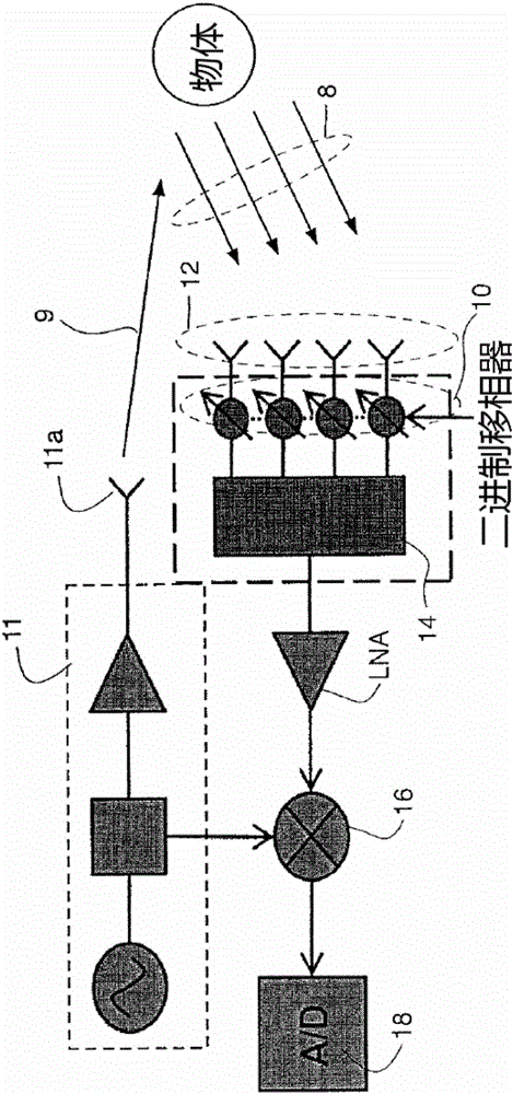
[0024] figure 1 Shows the block diagram of CAR, in order to simplify the hardware used, there is only CAR encoding on the receiving side. The antenna element 11 a associated with the radar transmitter 11 transmits the radar signal 9 . The radar signal 9 covers a field of view (FOV), and one or more objects within the FOV scatter energy, wherein the scattered energy 8 is received by a receiving radar antenna element 12 associated with the radar receiver. In some embodiments, the radar transmitter and radar receiver may share an antenna element (which, with appropriate switching, isolates the receiver from the relatively high energy signal normally emitted by the transmitter to prevent the high energy signal from damaging the reception. device). For implementation, the array of receive radar antenna elements 12 is preferably a two-dimensional array, but for analysis and simulation, a one-dimensional array is more convenient and may be used in implementation.

[0025] Each rec...


PUM


Abstract

A radar system in which Coded Aperture Radar processing is performed on received radar signals reflected by one or more objects in a field of view which reflect a transmitted signal which covers a field of view with K sweeps and each sweep including Q frequency changes. For Type II CAR, the transmitted signal also includes N modulated codes per frequency step. The received radar signals are modulated by a plurality of binary modulators the results of which are applied to a mixer. The output of the mixer, for one acquisition results in a set of QK (for Type I CAR) or QKN (for Type II CAR) complex data samples, is distributed among a number of digital channels, each corresponding to a desired beam direction. For each channel, the complex digital samples are multiplied, sample by sample, by a complex signal mask that is different for each channel.

Description

[0001] Cross References to Related Applications [0002] This application claims priority and benefit to US Provisional Patent Application No. 61 / 912,990, filed December 6, 2013, entitled "Method and Apparatus for Processing Coded Aperture Radar Signals." The disclosure of that US Provisional Patent Application No. 61 / 912,990 is incorporated herein by reference. This application also claims priority and benefit to US Patent Application No. 14 / 561,111 filed December 4, 2014, the entire disclosure of which is incorporated herein by reference. [0003] This application is related to US Patent Application No. 13 / 490,607 filed on 06 / 07 / 2012, entitled "Coded Aperture Beam Analysis Method and Apparatus", the disclosure of which is incorporated herein by reference. [0004] This application is also related to US Patent Application No. 13 / 725,621 filed on December 21, 2012, entitled "Coded Aperture Beam Analysis Method and Apparatus", the disclosure of which is incorporated herein by re...

Claims


Application Information

Patent Timeline
Patent Type & Authority Applications(China)
IPC IPC(8): G01S13/90G01S7/28
CPCG01S13/42G01S13/58G01S2013/0236G01S7/356
Inventor 乔纳森·J·林奇Z·A·徐彦丞·权
Owner HRL LAB
Why Eureka
Try Eureka