Bedside table

A bedside table and cabinet body technology, applied in the field of bedside table, can solve problems such as high cost and inconvenience, and achieve the effect of improving continuous working performance and reliability

Inactive Publication Date: 2016-08-24
NORTH CHINA UNIVERSITY OF SCIENCE AND TECHNOLOGY
View PDF5 Cites 1 Cited by
  • Summary
  • Abstract
  • Description
  • Claims
  • Application Information

AI Technical Summary

Problems solved by technology

Since embedded systems often arrange electrical components such as PCB boards, circuit chips, and power adapters in the housing, for heat dissipation considerations, the surface of the housing is often provided with pores or grooves. Over time, dust or dirt will inevitably enter the housing. The internal PCB board or the electronic components on the PCB board will pollute the chip and cause the device to fail. If it is manually removed, the cost is high and it is inconvenient

Method used


Image

  • Bedside table
  • Bedside table
  • Bedside table

Examples


Embodiment 1

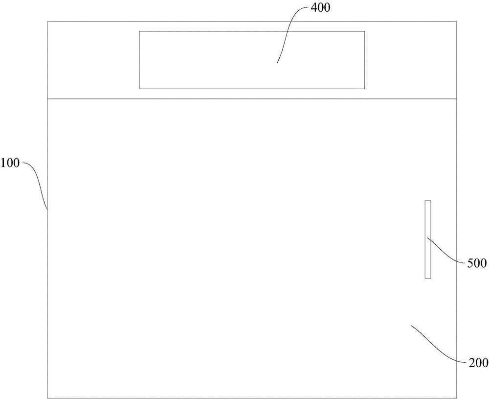
[0033] figure 1 It is a schematic diagram of the bedside cabinet in Embodiment 1. In the figure, the meanings of each reference sign are as follows: 100 cabinet body; 200, cabinet door; 400, control panel; 500, door handle.

[0034] The bedside table according to the embodiment of the present invention includes: a cabinet body 100, a cabinet door 200, a controller ( figure 1 not shown in), the control panel 400,

[0035] The cabinet door 200 is pivotally mounted on the cabinet body 100;

[0036] The controller is located in the cabinet 100;

[0037] The control panel 400 is arranged on the cabinet body 100 and on the top of the cabinet door 200, and the control panel 400 is connected with the controller.

[0038] The door handle 500 is provided on the cabinet door 100 .

Embodiment 2

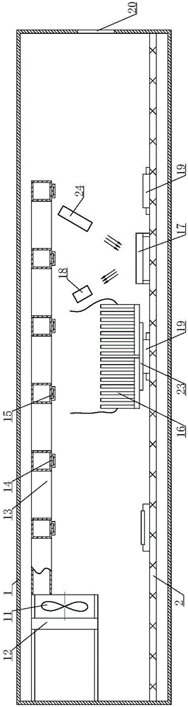
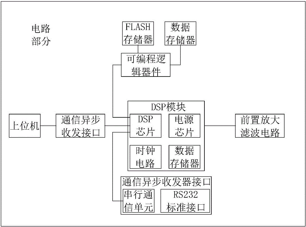
[0040] figure 2It is a structural schematic diagram of Embodiment 2 of the present invention; image 3 It is a structural schematic diagram of the circuit part in Embodiment 2 of the present invention; Figure 4 is a partial view of the self-adaptive air outlet in embodiment 2; Figure 5 It is a partial view of the element cooling fin in Embodiment 2;

[0041] In the figure, the meanings of each reference mark are as follows: 1. Driver housing; 2. PCB circuit board; 11. Cleaning air intake device; 12. Filter device; 13. Cleaning pipeline; 14. Self-adaptive air outlet; 15 , bimetal sheet; 16, heat sink single body; 17, reflective mirror surface; 18, photosensitive switch; 19, circuit element; 20, air exhaust port; 23, insulating heat conductor;

[0042] The controller includes a housing and a PCB board arranged in the housing; circuit elements are arranged on the PCB board,

[0043] The controller also includes a dust cleaning system. The dust cleaning system includes a fi...

Embodiment 3

[0064] Image 6 It is a structural schematic diagram of the heat sink in Embodiment 3 of the present invention; in the figure, the meanings of the reference signs that have appeared in the drawings used in Embodiment 2 follow the meanings in the drawings of Embodiment 2, and the newly appearing reference numerals The meanings expressed are as follows;

[0065] The difference between this embodiment and embodiment 2 is:

[0066] The individual heat sinks 16 are all arranged on an insulating heat conductor 23 , and the individual heat sinks 16 are divided along a circle.

[0067] The insulated heat conductor 23 can be an insulating layer attached to a metal material, so that the individual heat sinks 16 are insulated from each other without significantly reducing the thermal conductivity, so that the individual heat sinks 16 of the heat sink form a capacitor.


PUM


Abstract

The invention provides a bedside table. The bedside table comprises a table body, a table door, a controller and a control panel, wherein the table door is installed on the table body in a pivoted mode, the controller is arranged in the table body, and the control panel is arranged on the table body, located on the table door and connected with the controller. The bedside table is simple in structure.

Description

technical field [0001] The invention relates to the technical field of furniture, in particular to a bedside table. Background technique [0002] Among related technologies, smart furniture is becoming more and more popular. The core control component of smart furniture is the PCB board embedded in the housing. Since embedded systems often arrange electrical components such as PCB boards, circuit chips, and power adapters in the housing, for heat dissipation considerations, the surface of the housing is often provided with pores or grooves. Over time, dust or dirt will inevitably enter the housing. The internal PCB board or the electronic components on the PCB board will pollute the chip and cause the device to fail. If it is manually removed, the cost is high and it is inconvenient. Contents of the invention [0003] The present invention aims to solve one of the technical problems in the related art at least to a certain extent. [0004] For this reason, an object of ...

Claims


Application Information

Patent Timeline
Patent Type & Authority Applications(China)
IPC IPC(8): A47B79/00A47B97/00
CPCA47B79/00A47B97/00
Inventor 周晶张诺焦晶晶
Owner NORTH CHINA UNIVERSITY OF SCIENCE AND TECHNOLOGY
Why Eureka
Try Eureka