
Rapid-positioning bending machine

A bending machine, fast technology, applied in the direction of metal processing, metal processing equipment, safety equipment, etc., can solve the problems of dead angle of sight, easy to cause accidents, poor bending quality, etc., to improve positioning accuracy, prevent safety accidents, The effect of preventing false pressure

Inactive Publication Date: 2016-08-24
CHENGDU MATSUKAWA METAL MATERIALS
View PDF6 Cites 9 Cited by
  • Summary
  • Abstract
  • Description
  • Claims
  • Application Information

AI Technical Summary

Problems solved by technology

The positioning line needs to be drawn before the plate enters the bending machine. The existing bending machine needs to manually position the plate through the operator after the lined plate is extended into the bending machine. There are very high requirements, and it is easy to cause problems such as low bending efficiency and poor bending quality; and in this process, the operator is located in front of the bending equipment, and behind the bending equipment, due to the occlusion of the bending equipment, a blind angle of sight is formed. People behind the bending equipment or other objects protrude into the bending equipment template, which is easy to cause accidents
The existing bending equipment cannot prevent such accidents, and the efficiency and accuracy of the existing bending equipment are not high in the alignment of the plates

Method used


Image

  • Rapid-positioning bending machine
  • Rapid-positioning bending machine
  • Rapid-positioning bending machine

Examples


Embodiment Construction

[0014] In order to make the objectives, technical solutions and advantages of the present invention clearer, the present invention will be further described in detail below with reference to the accompanying drawings.

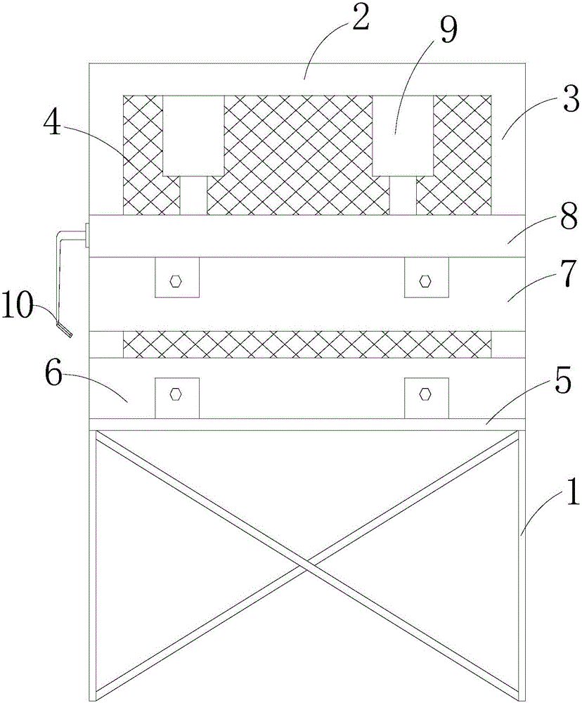
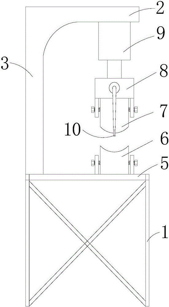
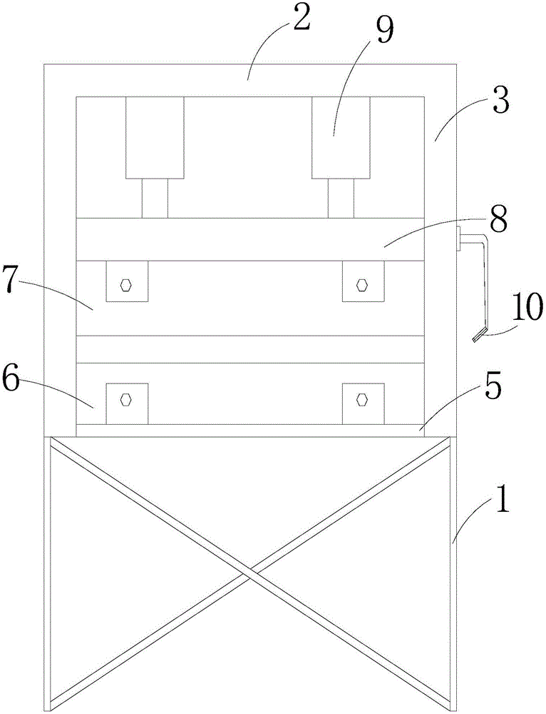
[0015] Such as Figure 1-3 As shown, the present invention provides a fast positioning bending machine, including a lower bracket and an upper bracket. The upper bracket is fixedly connected to the upper side of the lower bracket through a column. There are two columns, and a protective net is installed between the columns. A bending platform is installed on the surface. The upper surface of the bending platform is fixed with a lower bending die by bolts. The upper bending die is equipped with a bending upper die that is compatible with the lower bending die. The head is fixedly connected, and the pressure head is installed at the lower part of the upper bracket through a hydraulic device, which prevents unrelated persons from extending their hands or other irrele...


PUM


Abstract

The invention relates to the technical field of panel processing machinery, and discloses a rapid-positioning bending machine, which comprises a lower support frame and an upper support frame. The upper support frame is fixedly connected with one side of the upper part of the lower support frame through stand columns; two stand columns are arranged; a protective net is arranged between the stand columns; a bending platform is arranged on the upper surface of the lower support frame; a bending lower die is fixed on the upper surface of the bending platform through bolts; a bending upper die matched with the bending lower die is arranged above the bending lower die; the bending upper die is fixedly connected with a pressure head through bolts; the pressure head is arranged under the upper support frame through hydraulic devices; an infrared ray laser positioner is arranged at one end of the pressure head; laser emitted by the infrared ray laser positioner is projected on the upper surface of the bending lower die. The rapid-positioning bending machine is simple in structure and simple and safe to use, and can be used for rapidly positioning panels to be bent, so that the accuracy and the efficiency in bending the panels are improved.

Description

Technical field [0001] The invention relates to the technical field of plate processing machinery, in particular to a fast positioning bending machine. Background technique [0002] Bending machine is a common machining equipment used for bending steel plate. The working principle is to apply pressure to the plate through the mold, thereby deforming the plate and achieving the purpose of bending. Before the sheet enters the bending machine, a positioning line needs to be drawn. The existing bending machine needs to manually position the sheet by the operator after the lined sheet is extended into the bending machine. This manual positioning process has an impact on the operating skills of the operator There are very high requirements, which easily cause problems such as low bending efficiency and poor bending quality; and in this process, the operator is in front of the bending equipment, and the blind angle of the line of sight is formed behind the bending equipment due to the o...

Claims


Application Information

Patent Timeline
Patent Type & Authority Applications(China)
IPC IPC(8): B21D5/06B21D55/00B21C51/00
CPCB21D5/06B21C51/00B21D55/00
Inventor 周建川
Owner CHENGDU MATSUKAWA METAL MATERIALS
Learn More