Rear-mounted feeding digital controlled lathe

A CNC lathe, post-mounted technology, applied in the field of machinery, can solve problems such as low work efficiency, pollution, and hydraulic oil in the fuel tank, and achieve the effect of small footprint

Inactive Publication Date: 2016-08-24
慈溪市小旋风数控机械有限公司
View PDF0 Cites 3 Cited by
  • Summary
  • Abstract
  • Description
  • Claims
  • Application Information

AI Technical Summary

Problems solved by technology

[0002] At present, when the common CNC lathes process workpieces, most of them use manual assistance for loading. In this manual loading process, the labor intensity of workers is high, the work efficiency is low, and the quality of products is difficult to guarantee. In addition, frequent Manual operation will have potential safety hazards. At the same time, when processing parts, the iron filings and coolant used to cool the parts cannot be discharged from the front end of the spindle, while the iron filings and coolant discharged from the rear end of the spindle will cause iron Chips and coolant contaminate V-belts, pulleys, gears, motors and other components at the rear of the headstock of the lathe, making the contaminated components easily damaged and contaminating the hydraulic oil in the oil tank

Method used


Image

  • Rear-mounted feeding digital controlled lathe
  • Rear-mounted feeding digital controlled lathe
  • Rear-mounted feeding digital controlled lathe

Examples


Embodiment Construction

[0022] The following are specific embodiments of the present invention and in conjunction with the accompanying drawings, the technical solutions of the present invention are further described, but the present invention is not limited to these embodiments.

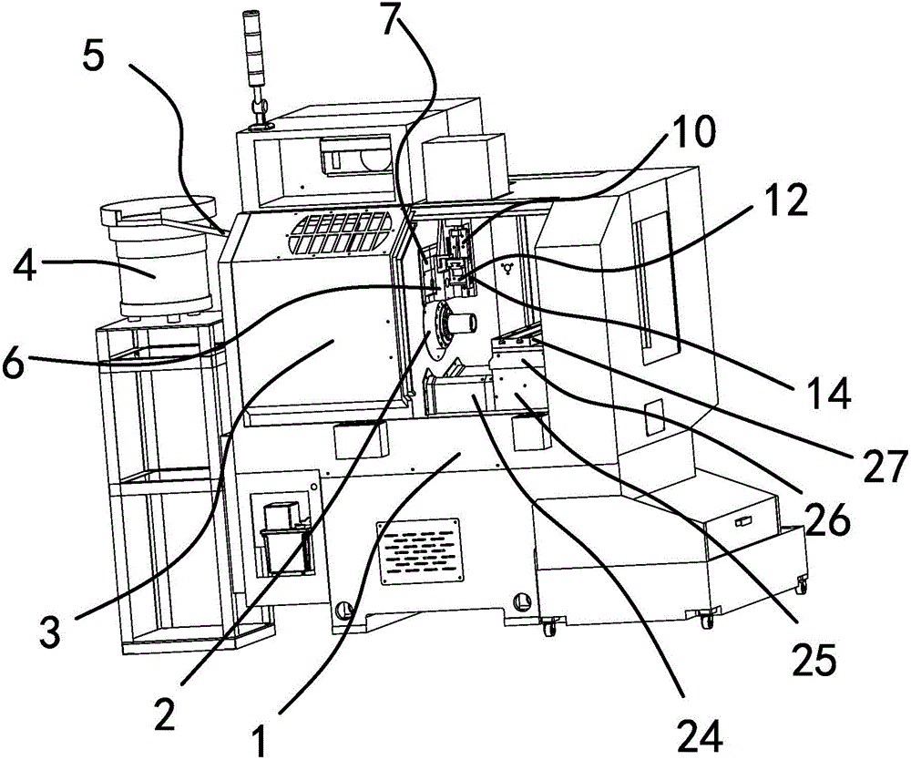
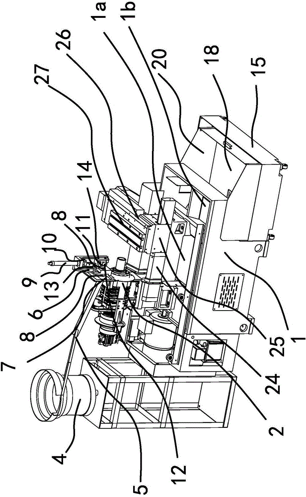
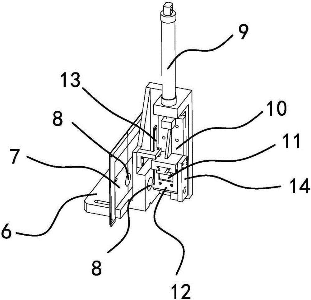
[0023] Such as Figure 1 to Figure 7 As shown, the rear-mounted feeding CNC lathe includes a frame 1, a machine cover 3 and a main shaft 2 located in the machine cover 3 are installed on the frame 1, and a slide rail 24 is also provided on the frame 1, and the slide rail 24 is located on the main shaft 2. In the front, a horizontal support plate 25 is slidably connected to the slide rail 24, a longitudinal support plate 26 is slidably connected to the transverse horizontal plate 18, and a workbench 27 is installed on the longitudinal support plate 26. On the vibrating plate 4 where the workpiece is placed and the vibrating plate 4 is located behind the main shaft 2, the outlet end of the vibrating plate 4 is connected with...


PUM


Abstract

The invention provides a rear-mounted feeding numerical control lathe, which belongs to the field of mechanical technology. It solves the problem of inconvenient feeding of existing lathes. This post-feeding CNC lathe includes a frame on which a machine cover and a spindle located in the cover are installed. Slide rails are also provided on the frame, and a horizontal supporting plate is connected to the slide rails. It is connected with a longitudinal supporting plate, and a workbench is installed on the longitudinal supporting plate. There is a vibrating plate on one side of the frame and the vibrating plate is located behind the main shaft. , above the main shaft, there is a feeding mechanism that can be lifted vertically. The outlet end of the feeding channel is connected with the feeding mechanism. The plate is located under the main shaft and connected to the liquid outlet, and a recovery box is arranged on the other side of the frame and the recovery box is located under the liquid outlet. The invention has the advantages of simple structure and strong practicability.

Description

technical field [0001] The invention belongs to the technical field of machinery, and in particular relates to a post-feeding numerical control lathe. Background technique [0002] At present, when the common CNC lathes process workpieces, most of them use manual assistance for loading. In this manual loading process, the labor intensity of workers is high, the work efficiency is low, and the quality of products is difficult to guarantee. In addition, frequent Manual operation will have potential safety hazards. At the same time, when processing parts, the iron filings and coolant used to cool the parts cannot be discharged from the front end of the spindle, while the iron filings and coolant discharged from the rear end of the spindle will cause iron Chips and coolant contaminate V-belts, pulleys, gears, motors and other components at the rear of the headstock of the lathe, making the contaminated components easy to damage and contaminating the hydraulic oil in the oil tank...

Claims


Application Information

Patent Timeline
Patent Type & Authority Applications(China)
IPC IPC(8): B23B7/14B23B15/00B23Q11/10B23Q11/00
CPCB23B7/12B23Q7/00B23Q7/046B23Q11/0053B23Q11/1069
Inventor 沈建勇
Owner 慈溪市小旋风数控机械有限公司
Why Eureka
Try Eureka