Adjustable eccentric chuck

A technology of eccentric chucks and chucks, applied in the direction of chucks, etc., can solve the problems of low precision of eccentric parts, inconvenient processing and use, etc., and achieve the effect of strong versatility, convenient adjustment and high quality

Inactive Publication Date: 2016-08-24
江燕
View PDF6 Cites 10 Cited by
  • Summary
  • Abstract
  • Description
  • Claims
  • Application Information

AI Technical Summary

Problems solved by technology

[0008] The technical problem to be solved by the present invention is to provide an adjustable eccentric chuck to overcome the defects of low processing precision of eccentric parts and inconvenient processing and use in the adjustable eccentric chuck in the prior art

Method used


Image

  • Adjustable eccentric chuck
  • Adjustable eccentric chuck
  • Adjustable eccentric chuck

Examples


Embodiment 1

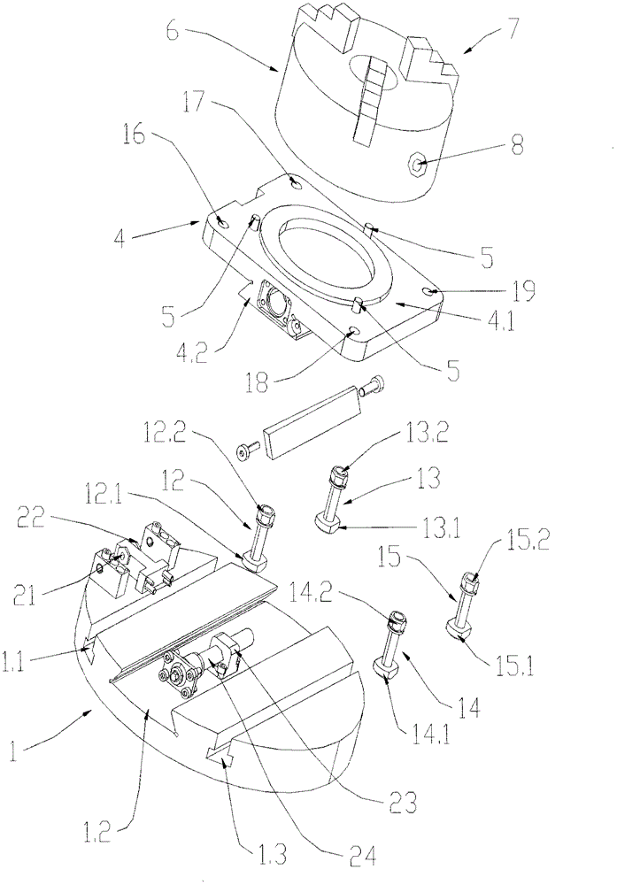
[0033] Such as image 3 , 4 , 5, and 6, the adjustable eccentric chuck of this embodiment includes a transition plate 1 fixed to the connecting plate of the lathe spindle with stud bolts, a gap adjustment mechanism 2, an eccentricity adjustment mechanism 3, a slider seat 4, two pairs of Locking bolts, screws 5, chuck body 6, jaws 7, jaw adjustment holes 8, measurement support 9 and a pair of measurement stops 10, 11; the transition plate is provided with a first T-shaped groove 1.1, a dovetail Slot 1.2, second T-shaped slot 1.3; the upper part 4.1 of the slider seat 4 is connected to the chuck body 6 through the screw 5, and the dovetail guide rail 4.2 at the lower part of the slider seat 4 cooperates with the dovetail groove 1.2 , the T-shaped ends 12.1, 13.1; 14.1, 15.1 of each pair of locking bolts 12, 13; The connection ends 12.2, 13.2, 14.2, 15.2 of , 14, 15 are fixedly connected to the connection holes 16, 17, 18, 19 of the slider seat 4 respectively; the ring grooves ...

Embodiment 2

[0043] Such as Figure 7 As shown, the second embodiment is basically the same as the first embodiment, the difference is that the workpiece contact surface 7.11 of the first jaw 7.1 in this embodiment is a plane; the second jaw 7.2 and the third jaw 7.3 The workpiece contact surfaces 7.12, 7.13 are right angle structures. Friction surfaces are provided on the plane and right-angle structures. The friction surface is several convex lines.

[0044] The embodiment of the present invention assists the up and down centering and clamping of the square workpiece, the first jaw 7.1 workpiece contact surface 7.11 presses the upper part of the square workpiece firmly, the second jaw and the third jaw right-angle workpiece contact surfaces 7.12 and 7.13 are opposite to each other After centering and clamping the shaped workpiece, it can be processed and turned. It is suitable for medium batch single and two-way eccentric square workpieces.

Embodiment 3

[0046] Such as Figure 8 As shown, the third embodiment is basically the same as the first embodiment, the difference is that an alarm device 100 is also provided on the chuck body 6 in this embodiment, and the alarm device includes an alarm 101, a battery 102 , the first contact piece 103 and the second contact piece 104; the first contact piece 103 and the second contact piece 104 are respectively arranged on the claw adjustment hole 8, and the first contact piece 103 is connected to the A battery 102, the battery provides power for the alarm through wires, the battery 102 is connected to the alarm 101, and the alarm is used to send out alarm reminders, and the alarm 101 is connected to the second contact piece 104 through wires. The above-mentioned first contact piece 103 and second contact piece 104 are not connected with the chuck body 6 .

[0047] The embodiment of the present invention prevents the occurrence of major safety accidents by setting an alarm device, that i...


PUM


Abstract

The invention discloses an adjustable eccentric chuck. The adjustable eccentric chuck comprises a transition disc fixed to a lathe spindle connecting disc. A chuck body is connected to the upper portion of a sliding block seat through screws. A dovetail guide rail on the lower portion of the sliding block seat is matched with a dovetail groove. T-shaped ends of each pair of locking bolts are located in a first T-shaped groove and a second T-shaped groove correspondingly. The connecting ends of the locking bolts are fixedly connected to connecting holes of the sliding block seat correspondingly. An eccentric distance adjusting mechanism comprises a nut seat and a screw rod linearly moving on the nut seat. A gap adjusting mechanism is arranged in the position, where the dovetail guide rail and the dovetail groove are matched, of one side of the dovetail guide rail. Rail grooves which are evenly and annularly distributed are formed in the chuck body, clamping jaws are arranged on the rail grooves, and movement of the clamping jaws is controlled by clamping jaw adjusting holes in the chuck body. A measurement support is fixed to the center of one side of the sliding block seat, measurement studs are arranged on the two sides of the measurement support correspondingly, and a pair of measurement stop blocks is fixed to the transition disc and opposite to the measurement support. According to the adjustable eccentric chuck, time and labor are saved, and high precision and high quality also can be achieved by a common lathe for machining eccentric parts.

Description

technical field [0001] The invention belongs to the field of lathe clamps, in particular to an adjustable eccentric chuck. Background technique [0002] In mechanical transmission, to convert rotary motion into linear motion, or convert linear motion into rotary motion, it is generally realized by crank slider (connecting rod) mechanism. Common eccentric shafts and cranks in actual production are its specific applications. instance of . The axis of the outer circle and the outer circle or the workpiece in which the axis of the outer circle and the inner hole are parallel and not coincident (off a certain distance from each other) is called an eccentric workpiece. Such as figure 1 As shown, the workpiece whose outer circle is eccentric to the outer circle is called the eccentric axis, and the distance between the two parallel lines is called the eccentricity e; figure 2 As shown, the workpiece whose inner hole is eccentric to the outer circle is called an eccentric sleeve...

Claims


Application Information

Patent Timeline
Patent Type & Authority Applications(China)
IPC IPC(8): B23B31/10
Inventor 江燕冯锋朱心怡包奇昊夏慧生王凯
Owner 江燕
Why Eureka
Try Eureka