
Multi-tool path layered and adjustable milling cutter

A technology for milling cutters and tool paths, which is applied in the direction of milling cutters, manufacturing tools, milling machine equipment, etc., can solve the problems of inability to realize continuous processing and low efficiency, and achieve the effects of saving time, labor and resources, improving efficiency, and having a wide range of applications

Inactive Publication Date: 2016-08-24
CHENGDU AIRCRAFT INDUSTRY GROUP
View PDF10 Cites 7 Cited by
  • Summary
  • Abstract
  • Description
  • Claims
  • Application Information

AI Technical Summary

Problems solved by technology

[0003] In order to solve the problems of low efficiency and inability to real

Method used


Image

  • Multi-tool path layered and adjustable milling cutter
  • Multi-tool path layered and adjustable milling cutter
  • Multi-tool path layered and adjustable milling cutter

Examples


Example Embodiment

[0022] The present invention will be further explained below in conjunction with the drawings.

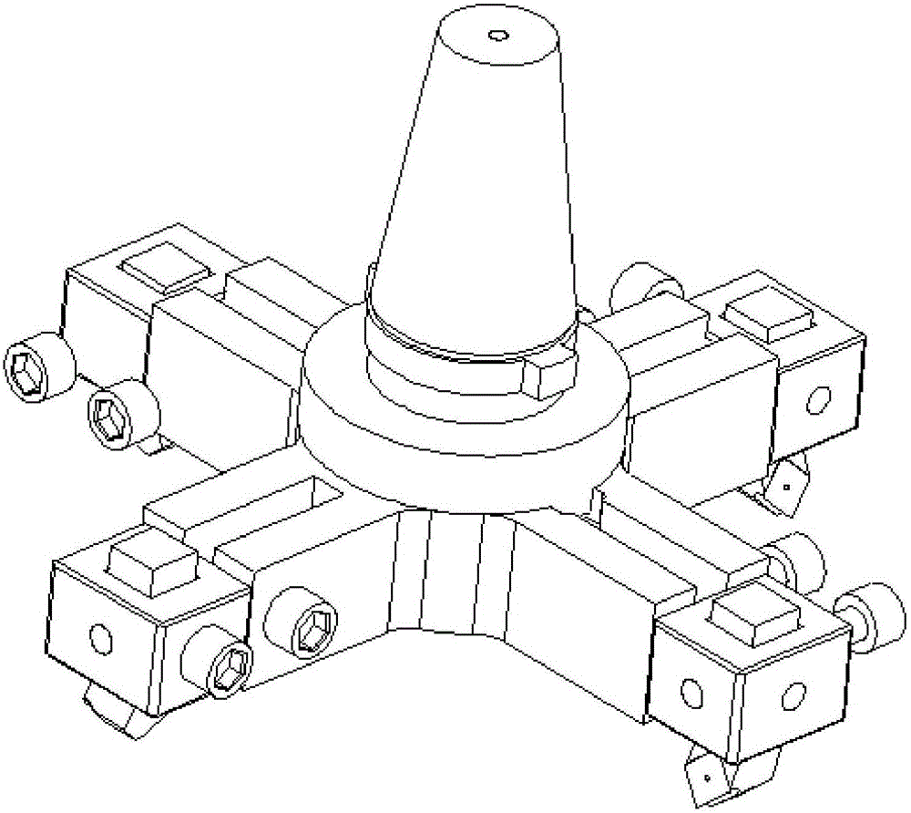
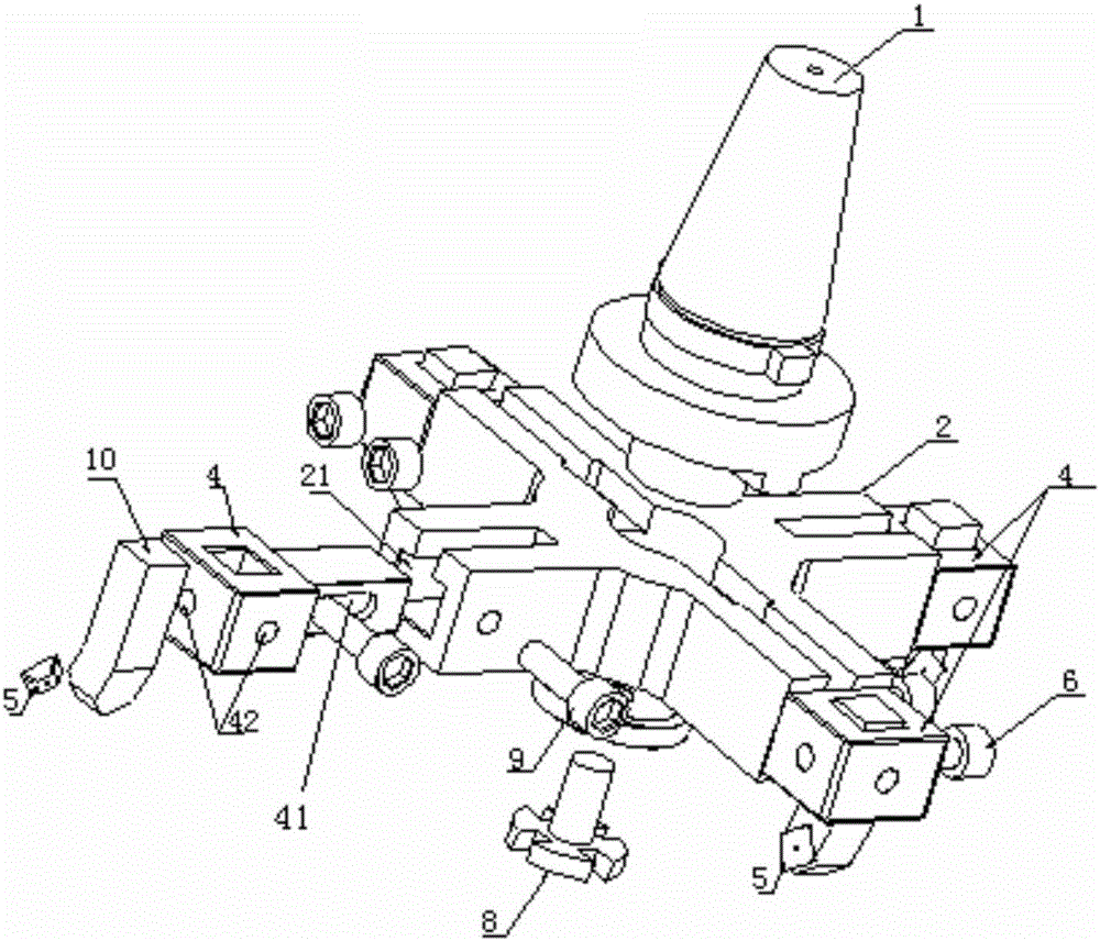
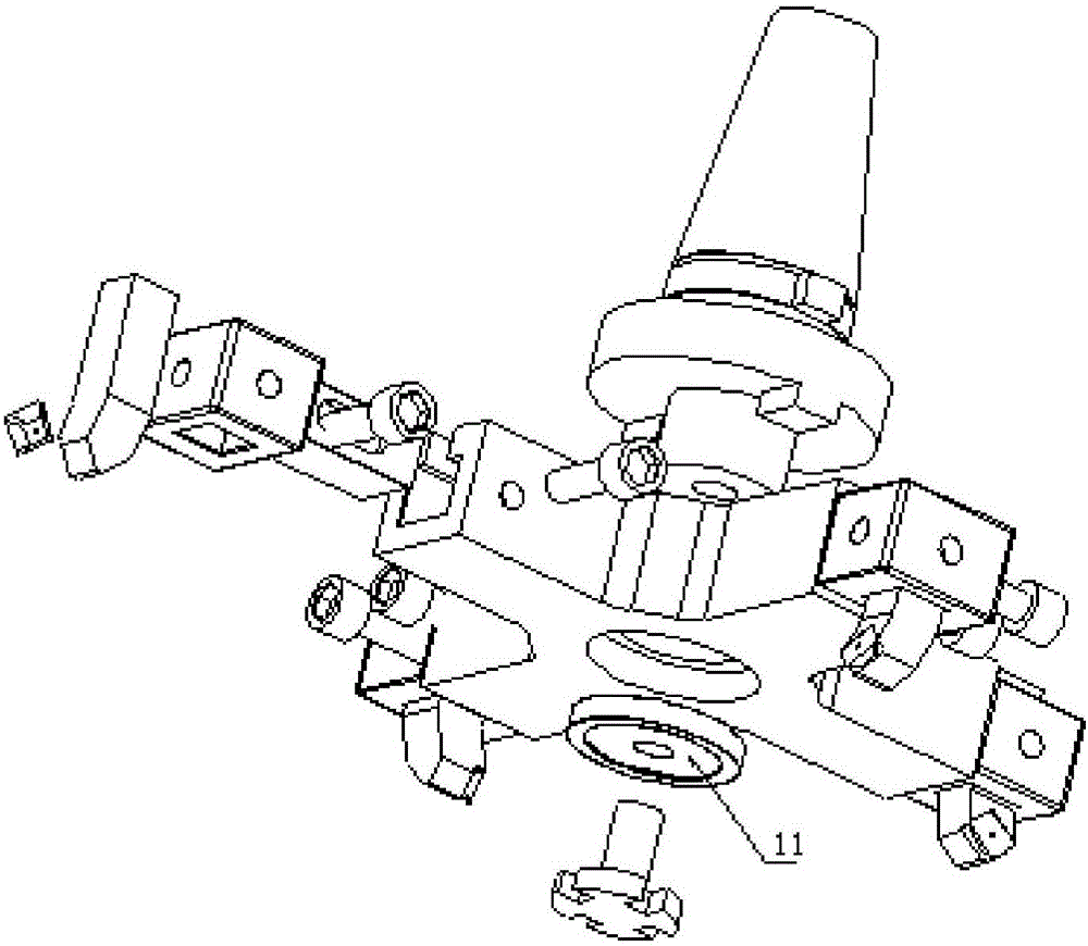
[0023] see figure 1 , figure 2 , image 3 , This embodiment is an example of installing four knives in the present invention:

[0024] In the figure, 1 is the chuck, 2 is the sliding support of the knife holder, 3 is the knife body 1, 4 is the knife holder, 5 is the blade, 6 is the fastening screw, 8 is the chuck screw, 9 is the safety screw, 11 is In the gasket, 21 is an adjustment groove, 41 is a safety groove, 22 is a safety hole, and 42 is a fastening screw hole.

[0025] The chuck 1 is tightly connected with the tool holder sliding support 2 through the gasket 11 and the chuck screw 8. The chuck 1 is connected with the machine tool spindle. The rotation of the spindle drives the chuck 1 to run at high speed, and the chuck 1 transmits the transmission through the keyway connection To the carriage sliding support 2. Each cutter body 1 has the same shape, material, and size. The cutt...


PUM


Abstract

The invention discloses a multi-tool path layered and adjustable milling cutter. The multi-tool path layered and adjustable milling cutter comprises a cutter rest sliding support, cutter rests and cutter bodies; a matching location hole is formed in the center of the cutter rest sliding support and cooperatively clamps a chuck of a machine tool; the cutter rest sliding support is provided with at least two adjusting grooves in the radial direction, one cutter rest is installed and fixed inside one adjusting groove, and the cutter bodies are fixedly installed on the cutter rests; the rotation radiuses of the cutter bodies installed on the cutter rests are progressively increased or reduced in the rotation direction. The milling cutter has the beneficial technical effects that Z-direction large-allowance multi-tool path continuous and layered milling can be realized on work-pieces in the surface milling process after tool setting of one time, one-step forming is realized, and the machining efficiency is improved; the diameters of tool paths can be adjusted in the X direction and the Y direction through support sliding grooves according to the sizes of blank surfaces, and the application range is wide; meanwhile, safety grooves and adjusting screws are arranged, and the phenomenon of cutter collision due to different materials and different shapes in the high-speed operation process of the machine tool can be effectively avoided.

Description

technical field [0001] The invention relates to a high-efficiency layered milling technology, in particular to a multi-tool track layered adjustable milling tool. Background technique [0002] When the vertical milling machine is pulling the blank or milling the smooth plane, the part is clamped on the vise, and the face milling cutter is used to mill along the tool track on the surface of the part. When the milling surface is required to be relatively wide, the existing traditional face milling The tool needs to add multiple tool tracks to complete the covering milling of the entire plane, so as to achieve the purpose of removing the surface allowance, so that there will be obvious tool tracks on the surface of the part, and the surface quality is not high. When the milling allowance is required to be relatively large, the cutting thickness and cutting width of the traditional face milling cutter cannot reach a large value due to the influence of cutting parameters such as ...

Claims


Application Information

Patent Timeline
IPC IPC(8): B23C5/00
CPCB23C5/00B23C2210/62
Inventor 胡蓉生王斌温良余泽
Owner CHENGDU AIRCRAFT INDUSTRY GROUP
Learn More