Self-compensation type floating three-jaw power chuck for cylindrical grinding machine

A cylindrical grinding machine, self-compensation technology, applied to grinding machines, machine tools designed for grinding the rotating surface of workpieces, grinding workpiece supports, etc. Small scope and other problems, to achieve the effect of saving production change time, facilitating production change adjustment, and avoiding production change errors

Inactive Publication Date: 2016-08-24
合肥华兴机器人有限公司
View PDF5 Cites 11 Cited by
  • Summary
  • Abstract
  • Description
  • Claims
  • Application Information

AI Technical Summary

Problems solved by technology

The existing chicken heart chuck adopts a circular eccentric cam to clamp the workpiece, and the clamping range is small without manual adjustment
For the growing automatic loading and unloading system of machine tool robots, this traditional clamping method cannot be easily applied to the automatic loading and unloading system of machine tool robots, which greatly hinders the application and promotion of automatic loading and unloading systems of grinding machine robots

Method used


Image

  • Self-compensation type floating three-jaw power chuck for cylindrical grinding machine
  • Self-compensation type floating three-jaw power chuck for cylindrical grinding machine
  • Self-compensation type floating three-jaw power chuck for cylindrical grinding machine

Examples


Embodiment Construction

[0024] In order to have a further understanding and understanding of the structural features of the present invention and the achieved effects, the preferred embodiments and accompanying drawings are used for a detailed description, as follows:

[0025] A self-compensating floating three-jaw power chuck for a cylindrical grinder, comprising:

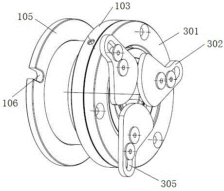
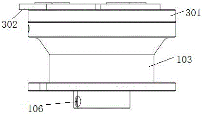
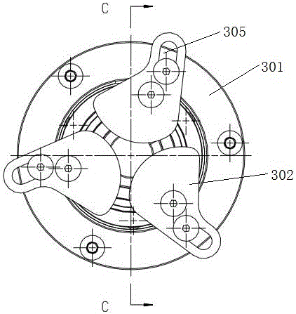
[0026] The casing, the casing includes a central sleeve 102 axially provided with a central through hole 101 and an outer shell 103 sleeved outside the central sleeve 102, and an accommodation cavity is formed between the central sleeve 102 and the outer shell 103; the center The inner wall of the through hole 101 is provided with a threaded hole 104 for fixing the chuck on the tip. Set on the top of the grinding machine through the central through hole 101, the threaded hole 104 through the central through hole 101 is provided with a fixing bolt, the chuck is fixed on the top, and the axial relative position between the jaws of the chuc...


PUM


Abstract

The invention discloses a self-compensation type floating three-jaw power chuck for a cylindrical grinding machine. The self-compensation type floating three-jaw power chuck comprises a shell, a bearing connecting unit and a floating clamping unit. The shell comprises a center sleeve axially provided with a center through hole and an outer shell arranged outside the center sleeve in a sleeving manner. A containing cavity is formed between the center sleeve and the outer shell. The bearing connecting unit is arranged in the containing cavity and comprises a roller pin one-way bearing, a middle bearing sleeve and a rolling bearing. The roller pin one-way bearing is arranged on the outer circle of the center sleeve in a sleeving manner, the middle bearing sleeve is fixed to the outer circle of the roller pin one-way bearing, and the rolling bearing is arranged on the outer circle of the middling bearing sleeve in a sleeving manner and connected with the inner circle of the outer shell. The floating clamping unit comprises a floating disc and clamping jaws arranged on the outer end face of the floating disc and used for clamping a workpiece. The floating disc is arranged on the end face of the outer shell through a gland in a floating manner. The design of sealing structures is achieved on the front portion and the rear portion of the containing cavity, and accordingly cutting fluid and other pollutants are prevented from entering the containing cavity during using. According to the self-compensation type floating three-jaw power chuck, a machine tool and robot automatic feeding and discharging system can conveniently conduct production exchange adjustment, the production exchange time is saved, and production exchange errors are avoided.

Description

technical field [0001] The invention relates to the field of grinding fixtures, in particular to a self-compensating floating three-jaw power chuck for an outer cylindrical grinding machine. Background technique [0002] The existing workpiece clamping device for cylindrical grinding machines generally uses a chicken heart chuck to manually clamp the workpiece before the workpiece is placed on the machine tool. The sweetheart chuck and the workpiece rotate together, and the angular position of the sweetheart chuck and the headstock lever needs to be considered during installation. The existing sweetheart chuck adopts a circular eccentric cam to clamp the workpiece, and the clamping range is small without manual adjustment. For the growing automatic loading and unloading system of machine tool robots, this traditional clamping method cannot be easily applied to the automatic loading and unloading system of machine tool robots, which greatly hinders the application and promot...

Claims


Application Information

Patent Timeline
IPC IPC(8): B24B41/06B24B5/35B24B5/04
CPCB24B41/067B24B5/04B24B5/355
Inventor 汪军钱康
Owner 合肥华兴机器人有限公司
Why Eureka
Try Eureka