
Delayed side core-pulling mechanism of injection mold

An injection mold and side core-pulling technology, which is applied in the field of delayed side core-pulling mechanisms of injection molds, can solve problems such as breakage, large tightness of side core-pulling sliders, and deformation of plastic parts.

Inactive Publication Date: 2016-08-24
ZHEJIANG KAIHUA MOLDS
View PDF5 Cites 5 Cited by
  • Summary
  • Abstract
  • Description
  • Claims
  • Application Information

AI Technical Summary

Problems solved by technology

[0002] After the plastic part is injection-molded by the injection mold, if the side wall of the plastic part is formed with a convex ring, a groove and a through hole at the same time, the existing technology usually uses a side core-pulling slider to simultaneously extract the convex ring, groove and through hole, while After the plastic part is injection molded, its tightness against the side core-pulling slider is large. If it is pulled out at the same time, it will easily cause the plastic part to deform or even be broken.

Method used


Image

  • Delayed side core-pulling mechanism of injection mold
  • Delayed side core-pulling mechanism of injection mold
  • Delayed side core-pulling mechanism of injection mold

Examples


Embodiment Construction

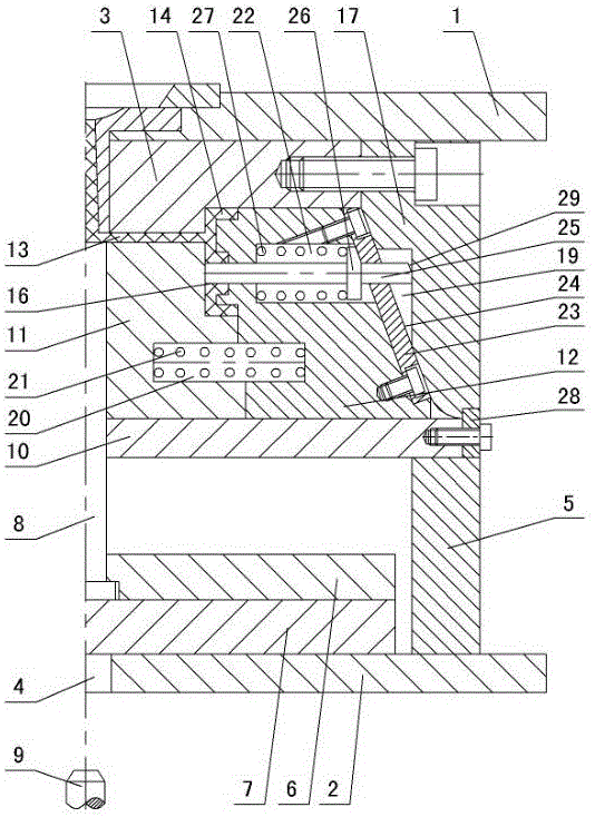
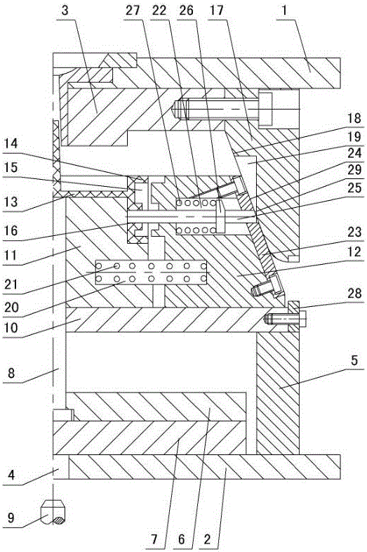
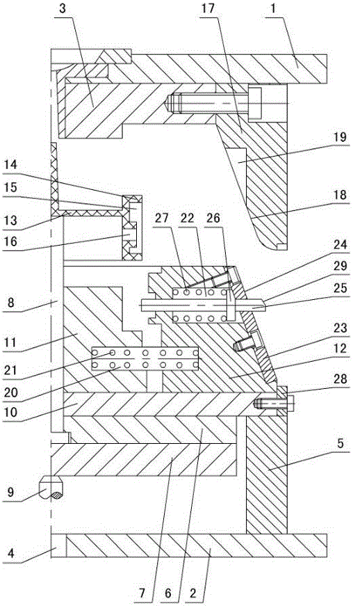
[0010] The invention relates to a core-pulling mechanism on the delayed side of an injection mold, such as figure 1 — image 3 As shown, it includes an upper doubler plate 1 and a lower doubler plate 2, a cavity 3 is set under the upper doubler plate, a perforation 4 is opened in the lower doubler plate, mold feet 5 are set on the lower doubler plate, and the lower doubler plate between the mold feet The upper ejector plate 6, the lower ejector plate 7 and the ejector pin 8 are arranged on the top, the ejector rod 9 of the injection machine passes through the perforation 4 and contacts the lower ejector plate, the backing plate 10 is set on the mold foot, the core 11 and side core pulling are set on the backing plate The slider 12 has an injection-molded plastic part 13 between the cavity 3, the core 11 and the side core-pulling slider 12. The side wall of the plastic part is formed with a convex ring 14, a groove 15 and a through hole 16. Its characteristics That is: a stopp...


PUM


Abstract

A delayed side core-pulling mechanism of an injection mold comprises an upper composite plate and a lower composite plate. A mold cavity is formed below the upper composite plate. A through hole is formed in the lower composite plate. The lower composite plate is provided with a mold pin, an upper ejector plate, a lower ejector plate and an ejector. A cushion plate is arranged on the mold pin, and the cushion plate is provided with a mold core and a side core-pulling sliding block. A plastic piece formed in an injection mode is arranged among the mold cavity, the mold core and the side core-pulling sliding block. A convex ring, a groove and a through hole are formed in the side wall of the plastic piece. The delayed side core-pulling mechanism is characterized in that a stop block is arranged below the upper composite plate; an inner slope and a right-angled slot are formed in the inner wall of the stop block; a sliding block spring is arranged in a spring slot which is formed between the mold core and the side core-pulling sliding block; a side pulling slot is formed in the side core-pulling sliding block, a fixing plate is arranged on the outer side of the side pulling slot, an outer slope is formed in the outer wall of the fixing plate, and the outer slope of the fixing plate makes contact with the inner slope of the stop block; a side core-pulling rod is arranged in the side pulling slot, and a baffle is arranged on the side core-pulling rod; a delay spring is arranged in the position, on the left side of the baffle, of the outer wall of the side core-pulling rod; one end of the side core-pulling rod penetrates through the side core-pulling sliding block to be matched with the through hole of the plastic piece; and the other end of the side core-pulling rod penetrates through the fixing plate to be matched with the right-angled slot of the stop block.

Description

technical field [0001] The invention relates to an injection mold, in particular to a core-pulling mechanism on the delayed side of the injection mold. Background technique [0002] After the plastic part is injection-molded by the injection mold, if the side wall of the plastic part is formed with a convex ring, a groove and a through hole at the same time, the prior art usually uses a side core pulling slider to simultaneously extract the convex ring, groove and through hole, while After the plastic part is injection-molded, its tightness against the side core-pulling slider is large, and if it is pulled out at the same time, the plastic part may be deformed or even broken. Contents of the invention [0003] The purpose of the present invention is to overcome the shortcomings of the prior art, and provide an injection mold with a simple structure by extracting the convex ring and the groove of the plastic part first, and then extracting the through hole of the plastic pa...

Claims


Application Information

Patent Timeline
IPC IPC(8): B29C45/33B29C45/40
CPCB29C45/332B29C45/4005
Inventor 李过
Owner ZHEJIANG KAIHUA MOLDS
Features
  • Generate Ideas
  • Intellectual Property
  • Life Sciences
  • Materials
  • Tech Scout
  • Unparalleled Data Quality
  • Higher Quality Content
  • 60% Fewer Hallucinations
Learn More