Cutting fluid waste liquid filtration sterilization deodorization regeneration equipment

A technology for cutting fluid and waste fluid, applied in filtration treatment, sterilization/microdynamic water/sewage treatment, water/sludge/sewage treatment, etc., can solve problems such as complicated procedures, high cost, and increased production cost, and achieve High adsorption efficiency, improved service life, and simple structure

Active Publication Date: 2018-05-22
HENAN ZONGHENG JINGGONG IND TECH INC
View PDF4 Cites 0 Cited by
  • Summary
  • Abstract
  • Description
  • Claims
  • Application Information

AI Technical Summary

Problems solved by technology

In order to improve the rust resistance of the cutting fluid during processing, the added sodium nitrite is easily converted into carcinogenic nitrosamines, and direct discharge will seriously endanger the water environment, and must be treated to meet the discharge standards stipulated by the state before discharge; because The price of cutting fluid is high, and the direct discharge of cutting fluid will increase the production cost. Therefore, the waste cutting fluid recovery and reuse device has a very high market prospect. The current equipment and methods still cannot simply and effectively treat the waste emulsified cutting fluid. for recycling
At present, it is generally recycled and handed over to the sewage treatment plant for treatment. The process is complicated and the cost is high.

Method used


Image

  • Cutting fluid waste liquid filtration sterilization deodorization regeneration equipment
  • Cutting fluid waste liquid filtration sterilization deodorization regeneration equipment
  • Cutting fluid waste liquid filtration sterilization deodorization regeneration equipment

Examples


Embodiment Construction

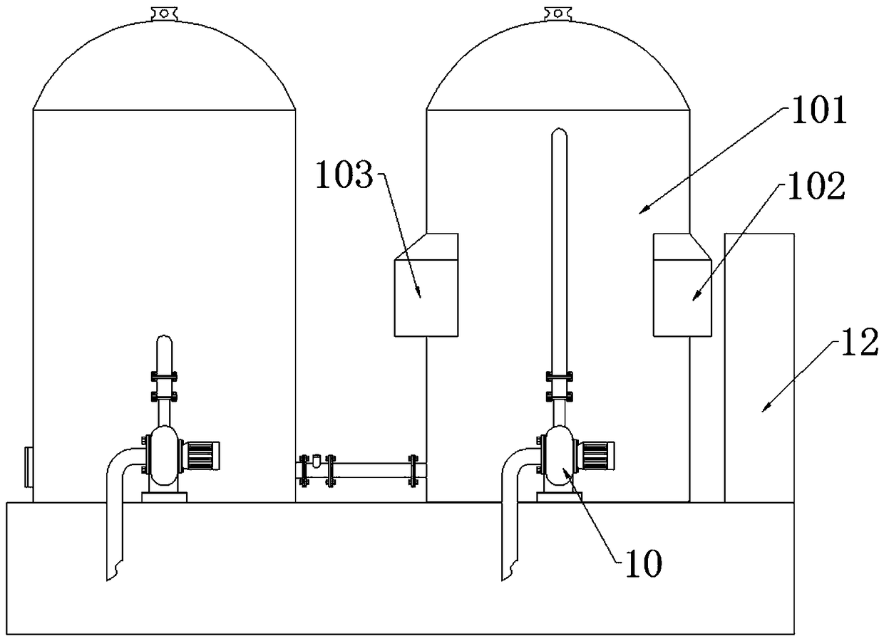
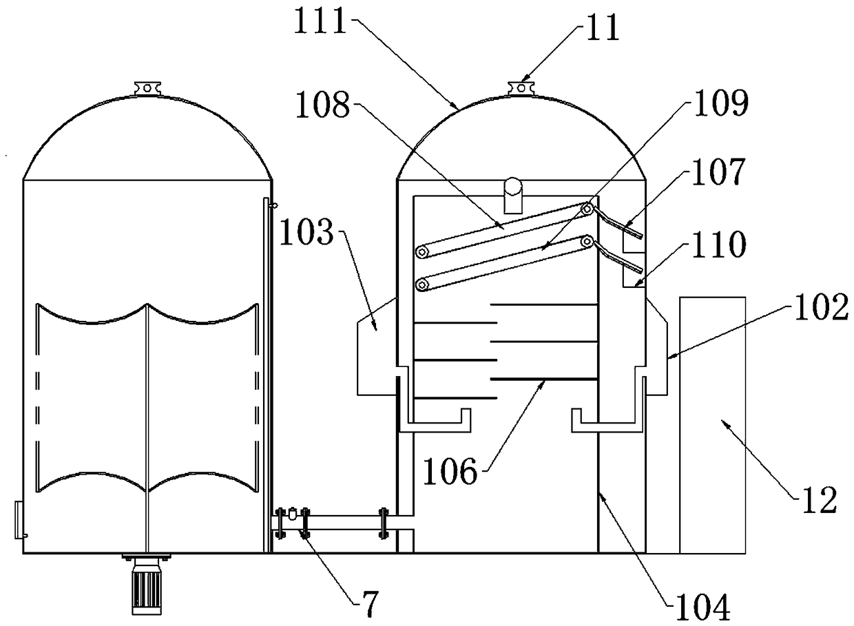
[0025] A cutting fluid waste liquid filtration sterilization deodorization regeneration equipment, see Figure 1-10 : comprising reaction kettle 101, inner tank 104, viscous adsorption collection device, metal adsorption collection device 108, reflux device, pump body, it is characterized in that: reaction kettle 101 inner cavity is provided with inner tank 104, and inner tank 104 inner cavity is from From top to bottom, a metal adsorption collection device 108, a sticky matter adsorption collection device 109 and a reflux device are arranged in sequence;

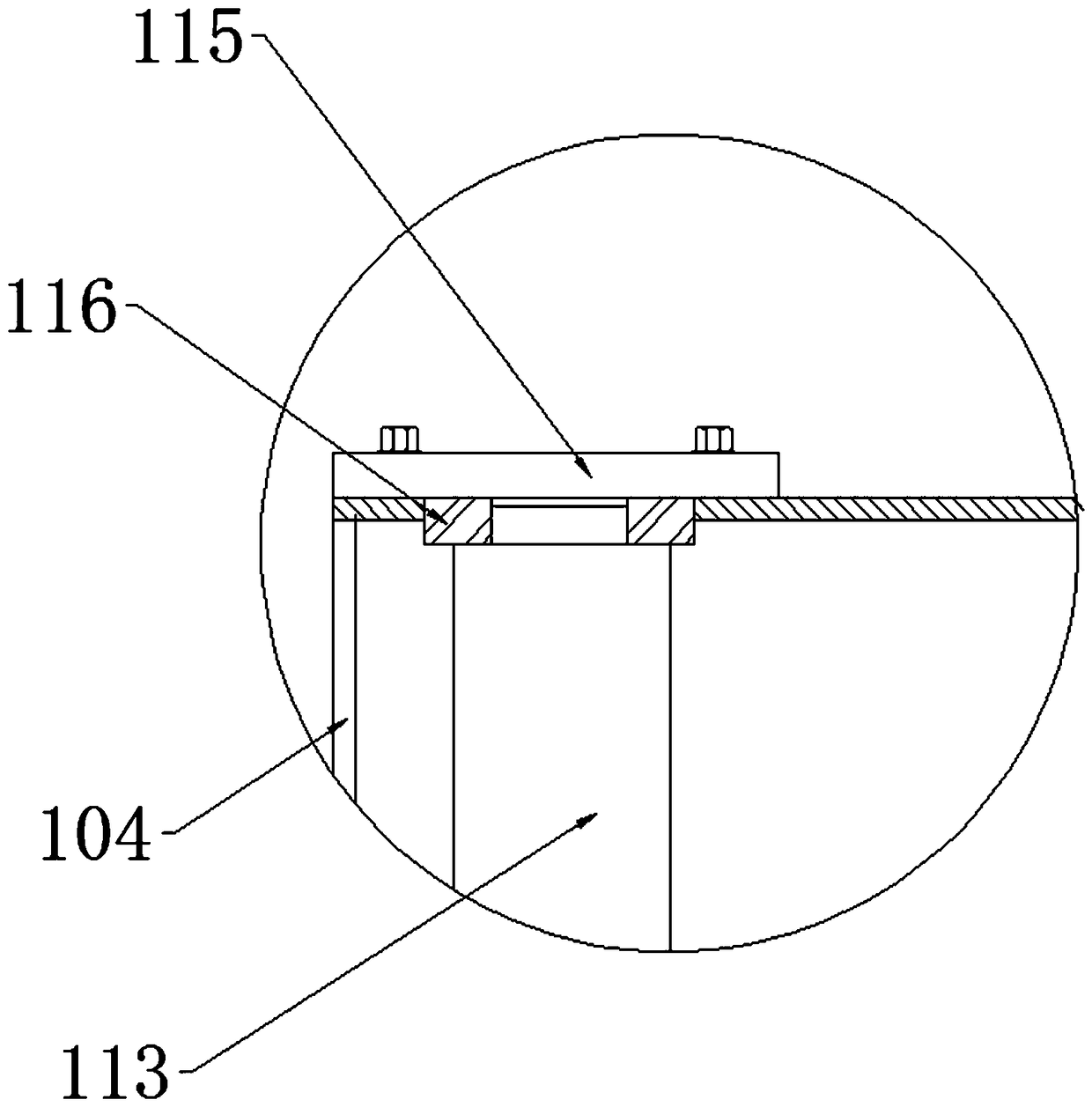
[0026] The metal adsorption collecting device 108 comprises a metal adsorption conveying device and a scraper 107, two supporting rollers 113 corresponding to each other are installed in cooperation with a magnetic conveying belt 112 to form a metal adsorbing conveying device, and the magnetic conveying belt 112 is provided with filter holes; one of the supporting rollers 113 Correspondingly connected to the rotating shaft ...


PUM


Abstract

The invention relates to filtration, sterilization, deodorization and regeneration equipment for waste cutting fluid. The filtration, sterilization, deodorization and regeneration equipment for waste cutting fluid comprises a reaction kettle, an inner pot, a viscous matter adsorption and collection device, a metal attraction and collection device, a reflux device and a pump, and is characterized in that the inner pot is arranged in an inner cavity of the reaction kettle, and the metal attraction and collection device, the viscous matter adsorption and collection device and the reflux device are arranged in an inner cavity of the inner pot in sequence from top to bottom; scrap iron is attracted through a magnetic conveying belt while waste cutting fluid is filtered through the metal attraction and collection device, metamorphic and decayed cutting fluid matter is filtered and collected by utilizing the characteristic that a viscous conveying belt can adsorb viscous matter, then a scraper is used for collection and removal, a conveying device is used for circulation, and thus the purpose of continuously removing decayed matter is achieved. The service life of the equipment is prolonged, the structure is simple, and the attraction and adsorption efficiency is high.

Description

technical field [0001] The invention relates to the field of machine tool coolant recovery, in particular to a cutting fluid waste liquid filtration, sterilization, deodorization and regeneration equipment. Background technique [0002] The machining industry generally uses cutting fluids to cool, lubricate, clean and prevent rust in the process of turning, grinding, cutting and rolling, so as to improve the quality of products and prolong the service life of machine tool tools. In addition to the hazards of general oily wastewater, waste cutting fluids are highly dispersed in water due to the action of surfactants, which are more easily absorbed by animals, plants, and aquatic organisms. Surfactants themselves are also harmful to organisms, and can also make some insoluble Toxic substances dissolved in water. In order to improve the rust resistance of the cutting fluid during processing, the added sodium nitrite is easily converted into carcinogenic nitrosamines, and direc...

Claims


Application Information

Patent Timeline
Patent Type & Authority Patents(China)
IPC IPC(8): C02F9/12
CPCC02F1/001C02F1/28C02F1/48C02F1/50C02F1/78C02F9/00
Inventor 毛军强赵凤轩
Owner HENAN ZONGHENG JINGGONG IND TECH INC
Why Eureka
Try Eureka