Tunnel grouting equipment and technology

A technology of grouting and tunneling, which is applied in the direction of tunnels, tunnel linings, mining equipment, etc., can solve the problems that are easy to cause quicksoil, quicksand, impact, collapse and instability of the tunnel top and side wall surrounding rock, and achieve relative position stability, Effect of reducing environmental pollution and maintaining permeability

Active Publication Date: 2020-03-27
北京中科中电电力工程管理有限公司
View PDF5 Cites 0 Cited by
  • Summary
  • Abstract
  • Description
  • Claims
  • Application Information

AI Technical Summary

Problems solved by technology

[0004] The above-mentioned existing technical solutions have the following defects: the exposure of the stratum can easily cause quicksand and quicksand, which will cause the top of the tunnel and the surrounding rock of the side wall to collapse and become unstable. Use the air pipe to blow off the sand scattered in the grouting hole. Insert the grouting pipe into the grouting hole and inject grout into the grouting pipe. When the air pipe blows off the grouting hole, the The blown dust has a great impact on the site environment and operators

Method used


Image

  • Tunnel grouting equipment and technology
  • Tunnel grouting equipment and technology
  • Tunnel grouting equipment and technology

Examples


Embodiment

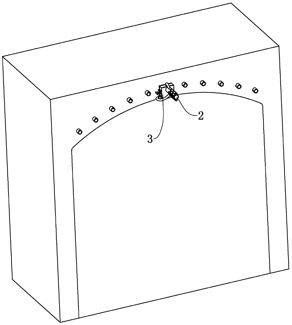
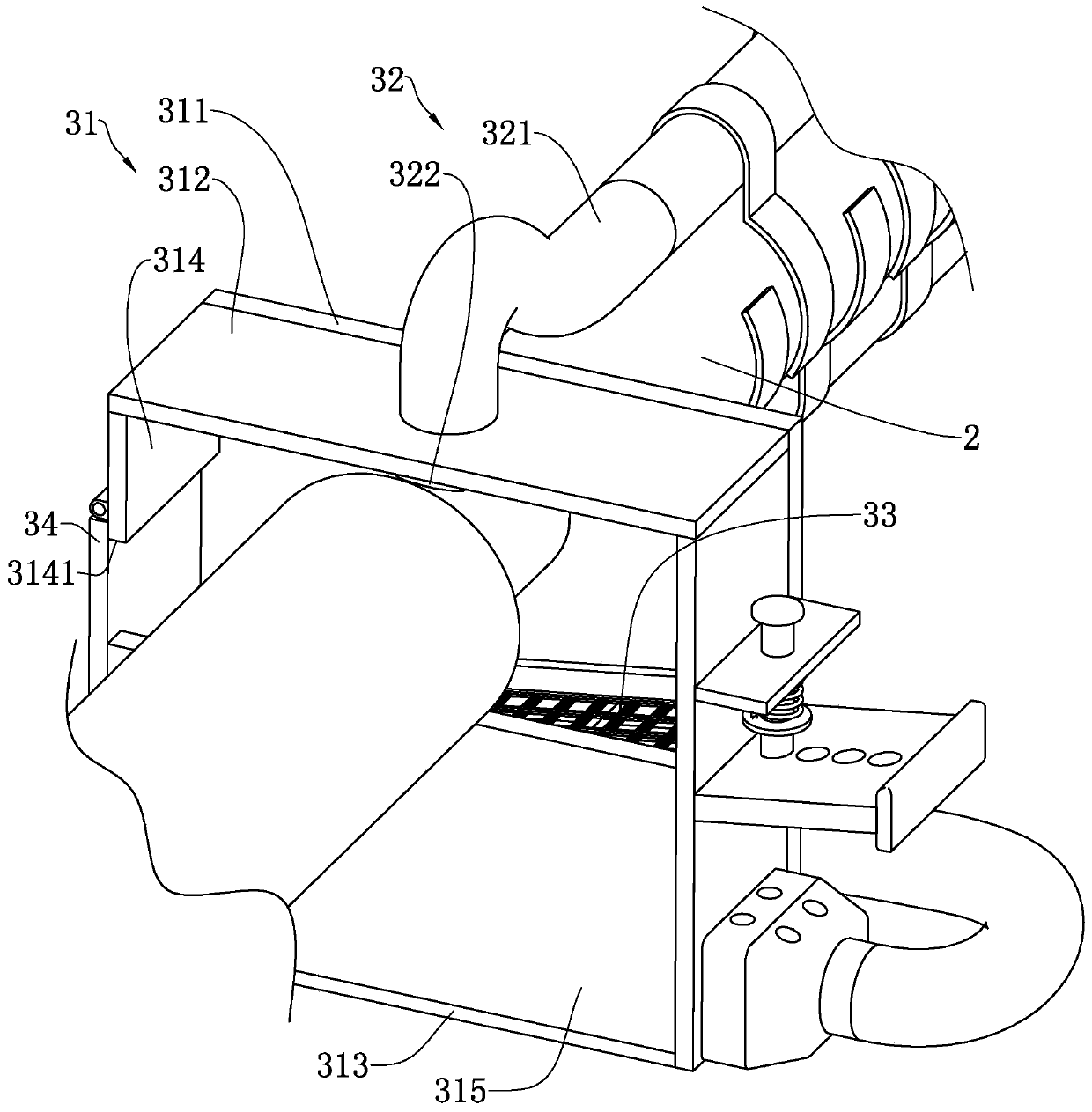
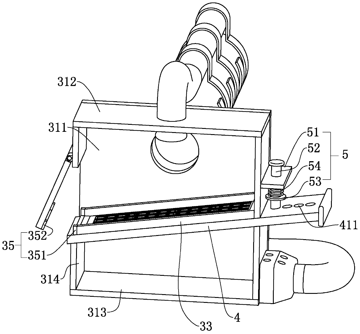
[0040] refer to figure 1 and figure 2 , discloses a tunnel grouting equipment for the present invention, including a blowpipe 2, a dust suppression mechanism 3 is arranged on the blowpipe 2, the dust suppression mechanism 3 includes a buckle cover 31 fixed on the blowpipe 2, and the opening of the buckle cover 31 faces the direction of the air outlet of the blowpipe 2 , the buckle cover 31 includes a rear plate 311, the rear plate 311 is a square plate, the upper and lower ends of the same surface of the rear plate 311 are respectively integrally formed with an upper side plate 312 and a lower side plate 313, between the upper side plate 312 and the lower side plate 313 Two vertical side plates 314 fixed on the rear plate 311 are provided, the vertical side plates 314 are fixed with the upper side plate 312 and the lower side plate 313, and the buckle cover 31 includes the vertical side plate 313 fixed on the lower side plate 313 and the vertical side plate 314. The front pl...


PUM


Abstract

The invention discloses a tunnel grouting equipment and technology. The tunnel grouting equipment comprises a blowing pipe, wherein one end of the blowing pipe communicates with a gas compressor; theblowing pipe is provided with a dust falling mechanism, wherein the dust falling mechanism comprises a buckle cover fixedly arranged on the blowing pipe, and the opening of the buckle cover faces theair outlet direction of the blowing pipe; a spraying mechanism is arranged on the buckle cover, wherein the spraying mechanism sprays water mist towards an inner cavity of the buckle cover; a fixing filter screen is fixedly arranged on the buckle cover, wherein the fixing filter screen is obliquely arranged; and a receding hole is formed in the buckle cover, a baffle covering the receding hole ishinged to the buckle cover, a pressing mechanism is arranged on the baffle, and an overflow hole is formed in the buckle cover. According to the tunnel grouting equipment and technology, effects of reducing flying dust when a grouting hole is cleaned can be achieved.

Description

technical field [0001] The invention relates to the technical field of tunnel construction reinforcement, in particular to a tunnel grouting equipment and process. Background technique [0002] With the continuous development of my country's national economic construction, engineering projects are becoming more and more complex, and various unfavorable engineering geological conditions have brought many difficult problems to the normal construction and operation of underground engineering. , Contingency problems are quite common and harmful. The treatment of such geological disasters usually adopts the grouting method. First, the area near the construction is reinforced by grouting, and then the construction is carried out to ensure the safe and efficient development of the project. [0003] The Chinese invention patent with the authorized notification number CN103993607B discloses a steel flower tube controlled grouting anti-slip composite structure and its rapid constructi...

Claims


Application Information

Patent Timeline
Patent Type & Authority Applications(China)
IPC IPC(8): E21D11/10E21F5/04B01D50/00
CPCE21D11/105E21F5/04B01D50/60
Inventor 胡建军杜宝龙赵天宝司铁利
Owner 北京中科中电电力工程管理有限公司
Why Eureka
Try Eureka