Blast Furnace Taphole Sliding Ventilation Device

A blast furnace tapping and air extraction device technology, applied in tuyere, dust collector, etc., can solve the problems of unfavorable installation of air duct support, deformation of cover body, low collection efficiency, etc., achieve simple and convenient control procedure, prevent deformation and damage, Simple effects with controls

Active Publication Date: 2018-08-31
武汉朗涤环保科技工程有限公司
View PDF2 Cites 0 Cited by
  • Summary
  • Abstract
  • Description
  • Claims
  • Application Information

AI Technical Summary

Problems solved by technology

[0004] 1) It is difficult to set up the air duct support for the exhaust duct of the fixed exhaust hood on the ground of the blast furnace casting yard, and the foundation of the air duct support is difficult to adapt to the actual situation of the casting yard
[0005] 2) The position of the fixed exhaust hood is fixed, it is located directly above the tap hole, and the cover body is baked at high temperature for a long time, which may easily cause deformation and damage of the cover body
[0006] 3) When the main iron ditch is excavated and repaired, the position of the exhaust hood is fixed, which hinders the hoisting of the truss truck in front of the furnace and the normal operation of the excavator
[0007] 4) The fixed exhaust hood is not conducive to the installation of the air duct bracket, so the general fixed exhaust hood has a small shape, a small area of ​​the hood, and a small dust collection range, resulting in diffuse smoke and low collection efficiency.

Method used


Image

  • Blast Furnace Taphole Sliding Ventilation Device
  • Blast Furnace Taphole Sliding Ventilation Device

Examples


Embodiment Construction

[0022] The present invention will be described in further detail below in conjunction with the accompanying drawings.

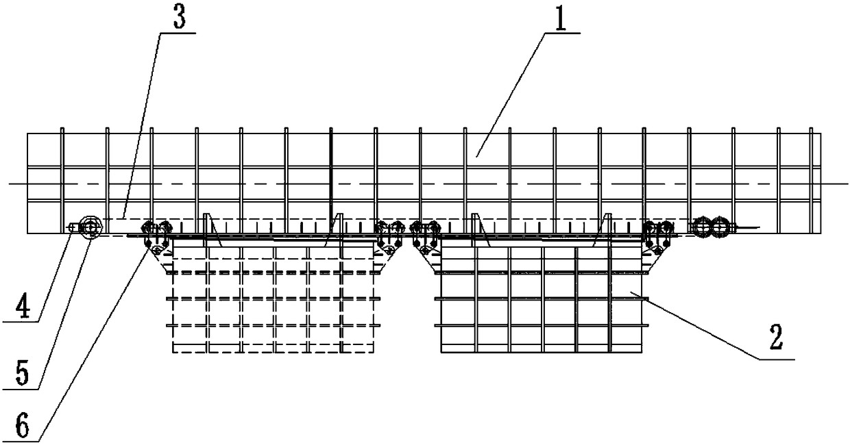
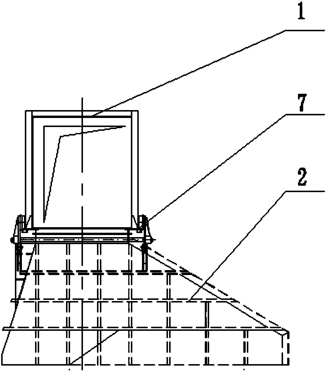
[0023] combined with figure 1 And attached figure 2 , a blast furnace taphole sliding exhaust device, which includes a rectangular beam exhaust pipe 1, a sliding exhaust fan 2, a wire rope 3, a power transmission device 4, a clamping device 5, a pulley 6 and a track 7; the rectangular The bottom of the beam exhaust pipe 1 is equipped with a track 7, and the top of the sliding exhaust fan 2 is equipped with a pulley 6; the pulley 6 is rollingly matched with the track 7; A power transmission device 4 is installed, and a steel wire rope 3 that can reciprocate around the power transmission device 4 is installed on the power transmission device 4; the steel wire rope 3 is connected with the sliding exhaust fan 2; the power transmission device 4 is also installed There is a clamping device 5 for keeping the steel wire rope 3 under tension.

[0024] As a prefere...


PUM


Abstract

The invention provides a sliding type air extracting device of a tap hole of a blast furnace. The sliding type air extracting device of the tap hole of the blast furnace facilitates construction in front of a furnace, can linearly move along a track in a reciprocating manner, is controlled by an operator in front of the furnace through an operating box, and is simple in control mode, small in maintenance workload and low in failure rate; and the tap hole is not easily blocked by materials. The sliding type air extracting device of the tap hole of the blast furnace comprises a rectangular beam air extracting tube, a sliding type air extractor, a steel wire rope, a power transmission device, a clamping device, a pulley and a track. The track is mounted on the lower part of the rectangular beam air extracting tube, the pulley is mounted on the upper part of the sliding type air extractor and is in rolling fit with the track; the power transmission device is further mounted on the lower part of the rectangular beam air extracting tube; the steel wire rope which can move in a reciprocating manner around the power transmission device is mounted on the power transmission device; the steel wire rope is connected with the sliding type air extractor; and the clamping device which is used for keeping tension force of the steel wire rope is further mounted on the power transmission device.

Description

technical field [0001] The invention relates to an environment treatment device for a taphole of a blast furnace casthouse in the metallurgical industry, in particular to a sliding air exhaust device for a blast furnace taphole. Background technique [0002] Since the 1970s, iron-making blast furnaces have developed towards large-scale development, and the production operation of the casthouse has undergone fundamental changes. With the extension of the casting time, the time of smoke and dust pollution has also been extended, and the amount of smoke and dust emitted is large, and the smoke particles are fine. The surrounding environment has a wide range of influences. If effective control measures are not taken, it will not only pollute the environment, but also seriously hinder the operation and safety of the casthouse, and at the same time, it will also be a great threat to the normal operation of equipment and instruments. The smoke and dust in the blast furnace casthou...

Claims


Application Information

Patent Timeline
Patent Type & Authority Patents(China)
IPC IPC(8): C21B7/22C21B7/16
CPCC21B7/16C21B7/22
Inventor 周志存余英陈兰洲綦杰
Owner 武汉朗涤环保科技工程有限公司
Why Eureka
Try Eureka