Transferring stitching device

A suture device and coil transfer technology, applied in textiles, papermaking, knitting, etc., can solve the problems of complicated procedures and many structural parts

Active Publication Date: 2016-08-24
浙江海润精工机械有限公司
View PDF8 Cites 2 Cited by
  • Summary
  • Abstract
  • Description
  • Claims
  • Application Information

AI Technical Summary

Problems solved by technology

The above method obviously requires more structural parts and complicated procedures

Method used


Image

  • Transferring stitching device
  • Transferring stitching device
  • Transferring stitching device

Examples


Embodiment 1

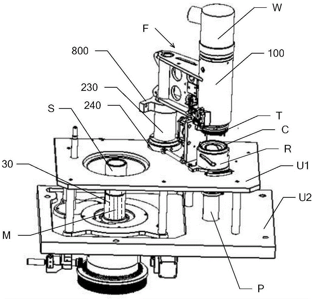
[0122]Step 800 includes: moving up the sock turning member M in the needle cylinder S to transfer the hosiery loop from the sock needle to the functional teeth and turning the sock, and then resetting the sock turning member M.

[0123] In this way, the hosiery loop can be transferred from the sock needle to the functional tooth and the sock can be turned over simply by moving up the sock turning member M, which greatly simplifies the process and structure. The structure of the sock member M is not limited, for example, it can be a solid rod member, a hollow pipe member and the like. However, in the process of transferring the socks from the needle cylinder S in the traditional method, a complex grabbing piece assembly must be used, wherein the grabbing piece is inserted on the sock line between the sock needles, so as to realize the transfer of the socks.

Embodiment 2

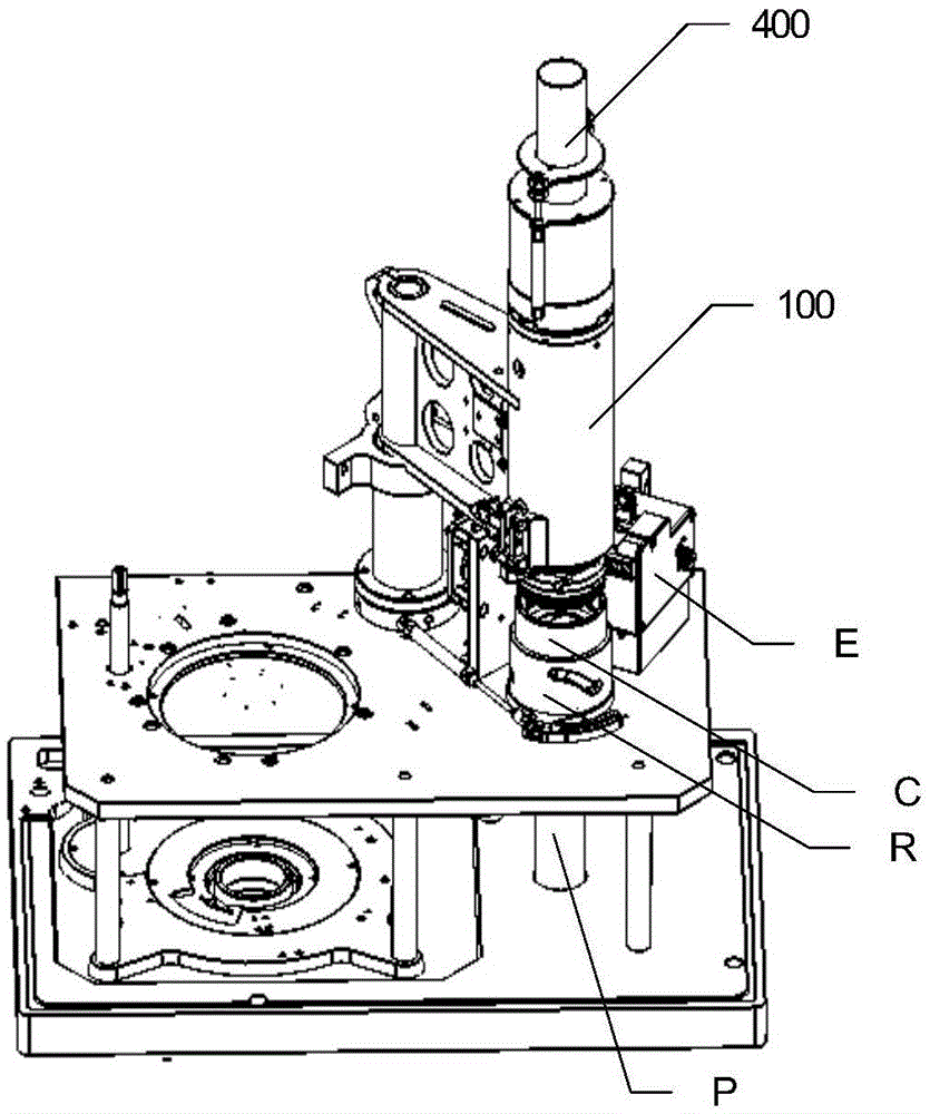
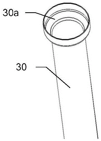
[0125] The transfer sewing device F can include an upper hosiery ring 400, a top hosiery tube 30 is provided in the syringe S, the lower end of the upper hosiery ring 400 or the upper end of the top hosiery tube 30 has a platform, and a sock turning part is arranged in the top hosiery tube 30 M.

[0126] Step 800 includes:

[0127] Step 810, move the upper sock part 400 downward and / or move the top sock tube 30 up so that the upper sock part 400 is in contact with the top sock tube 30, and then the upper sock part 400 moves up together with the top sock tube 30 to The hosiery loop is transferred from the hosiery needle to the functional teeth;

[0128] Step 820, reset the top sock tube 30, move up the sock turning part M in the needle cylinder S to turn the socks, and then reset the sock turning part M.

[0129] Because in step 810, the upper sock ring 400 moves upward together with the top sock tube 30 to complete the stitch transfer, it will be positioned above the stitche...


PUM


Abstract

The invention discloses a transferring stitching device which comprises a rotating rack, a center mounting pipe mounted on the rotating rack, and a transferring stitching head fixed on the center mounting pipe, wherein the transferring stitching head comprises a fixed half-tooth rack, a turning half-tooth rack, a turning half-tooth rack coil transferring assembly and a fixed half-tooth rack coil transferring assembly; a plurality of first functional teeth are arranged on the fixed half-tooth rack; at least one second functional tooth is arranged on the turning half-tooth rack; the turning half-tooth rack can turn over relative to the fixed half-tooth rack, so that the first functional teeth can be aligned with the second functional teeth; the first functional teeth are transferring stitching teeth, and stitching needle slots are formed in the outer surfaces of the first functional teeth. According to the transferring stitching device, multiple functions are realized within a limited space through reasonable layout of the components, so that compactness and miniaturization of the device are realized.

Description

technical field [0001] The invention relates to the field of hosiery machines. Background technique [0002] At present, when producing socks, it is generally first to produce semi-finished socks in the needle cylinder of the sock machine. On the head plate, and then use a sewing machine to sew the toe of the sock. The transfer device usually includes a transfer head, and the transfer head includes a fixed half rack, an inverted half rack and a plurality of transfer teeth. The reversible half rack can be turned over relative to the fixed half rack so that the transfer teeth installed on the two are aligned with each other, and then the hosiery line can be transferred. [0003] Specifically, in the process of transferring socks from the needle cylinder, it is first necessary to use the catch piece assembly, wherein the catch piece is inserted on the sock line between the sock needles, so as to realize the transfer of socks, and secondly, after the transfer, the socks If it...

Claims


Application Information

Patent Timeline
Patent Type & Authority Applications(China)
IPC IPC(8): D04B39/08
Inventor 姚先均
Owner 浙江海润精工机械有限公司
Why Eureka
Try Eureka