Light emitting device

A light-emitting device and excitation source technology, applied in the field of light sources, can solve the problems of insufficient brightness, low power of a single LED light source, and high use cost, and achieve the effect of a simple and compact overall structure

Active Publication Date: 2014-06-04
杨毅
View PDF22 Cites 3 Cited by
  • Summary
  • Abstract
  • Description
  • Claims
  • Application Information

AI Technical Summary

Problems solved by technology

But the problem is that the power of a single LED light source is low, and there is still the problem of insufficient brightness.
[0004] In the field of high-brightness light sources, high-pressure mercury lamps and xenon light sources are commonly used. Such light sources rely on ultra-short lamp arcs to have high brightness (energy density), but the problem is that their lifespan is only about 1000 hours, and the cost of use is very high.

Method used


Image

  • Light emitting device
  • Light emitting device
  • Light emitting device

Examples


Embodiment Construction

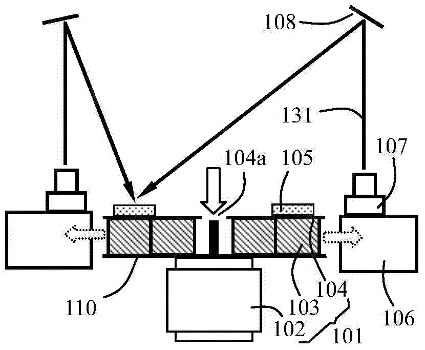
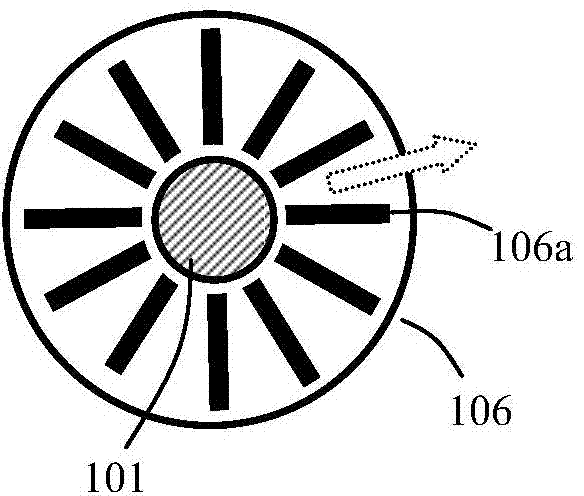
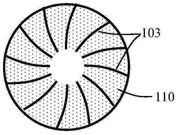
[0019] The present invention proposes a light-emitting device, the schematic diagram of which is shown in Figure 1a shown. The light-emitting device includes a centrifugal fan 101 , and the centrifugal fan includes a heat conduction rotating platform 104 , and the heat conducting rotating platform 104 is fixedly connected to the middle of a fan blade 103 of the centrifugal fan and rotates together with the fan blade 103 . Specifically, the fan blade 103 also includes a bottom plate 110, which is fixedly connected to the motor 102 of the centrifugal fan, so that the motor 102 can drive the fan blade 103 to rotate when it rotates. The top view of fan blade 103 and bottom plate 110 is as follows Figure 1c As shown, it can be seen that the fan blades are symmetrically distributed around the center of the circle, and the direction of each fan blade is along the radial direction and slightly curved in the clockwise direction, and each fan blade forms a cavity in the center.

[00...


PUM


Abstract

The invention provides a light emitting device. The light emitting device comprises a centrifugal fan, wherein the centrifugal fan comprises heat conduction rotary platforms, and the heat conduction rotary platforms are fixedly connected to the centers of fan blades of the centrifugal fan and rotate along with the fan blades. The light emitting device further comprises a wave length shifting layer covering the outer surfaces of the heat conduction rotary platforms and further comprises radiators located beside or around the centrifugal fan. Air blown out from the side faces of the centrifugal fan is transmitted along fins of the radiators and cools the radiators. The light emitting device further comprises an excitation source fixed to the radiators and a reflection device installed on the light emitting light path of the excitation source. Excitation light emitted from the excitation source is emitted to the wave length shifting layer through the reflection device in a reflected mode, and excitated light is emitted. The centrifugal fan provides rotation for the wave length shifting layer so that partial heat of the wave length shifting layer can be dissipated. Meanwhile, the centrifugal fan cools the heat conduction rotary platforms, air flow blown out can cool the radiators of the excitation source, and therefore the centrifugal fan can play multiple roles at the same time. The overall structure is simple and compact.

Description

technical field [0001] The invention relates to the field of light sources, in particular to a light emitting device. [0002] Background technique [0003] At present, light source technology has been applied in many fields, and the most widely used light sources are halogen lamps and fluorescent lamps. The biggest problem with these light sources is insufficient brightness. In recent years, the LED light source has developed rapidly. The blue LED is used to excite the yellow phosphor powder coated on the surface of the LED to generate white light. This light source has begun to be popular in the market. But the problem is that the power of a single LED light source is low, and there is still the problem of insufficient brightness. [0004] In the field of high-brightness light sources, high-pressure mercury lamps and xenon light sources are commonly used. Such light sources rely on ultra-short lamp arcs to have high brightness (energy density), but the problem is that t...

Claims


Application Information

Patent Timeline
Patent Type & Authority Applications(China)
IPC IPC(8): F21K2/00F21V29/02F21V29/67F21V29/70
Inventor 吴震
Owner 杨毅
Why Eureka
Try Eureka