A worm gear reducer

A worm reducer, worm gear technology, applied in belt/chain/gear, transmission parts, mechanical equipment and other directions, can solve the problems of high processing cost, can not be widely used, complex structure, etc., to achieve low cost, large transmission Smaller effect than output, volume

Active Publication Date: 2018-07-13
CHANGSHA AIKERUI GEAR MACHINERY
View PDF5 Cites 0 Cited by
  • Summary
  • Abstract
  • Description
  • Claims
  • Application Information

AI Technical Summary

Problems solved by technology

It is widely used in modern machinery. Among all kinds of reducers, the worm reducer is widely used. The structure of the worm reducer in the prior art is relatively complicated, and the processing cost is high, so it cannot be widely used.

Method used


Image

  • A worm gear reducer
  • A worm gear reducer
  • A worm gear reducer

Examples


Embodiment Construction

[0018] The following will clearly and completely describe the technical solutions in the embodiments of the present invention with reference to the accompanying drawings in the embodiments of the present invention. Obviously, the described embodiments are only some, not all, embodiments of the present invention. Based on the embodiments of the present invention, all other embodiments obtained by persons of ordinary skill in the art without making creative efforts belong to the protection scope of the present invention.

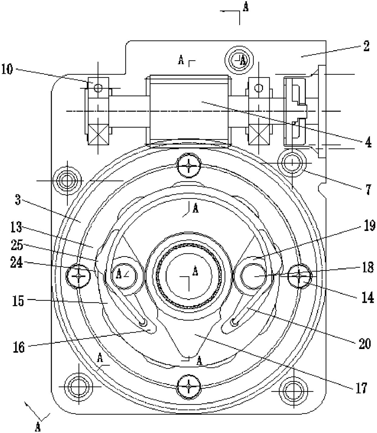
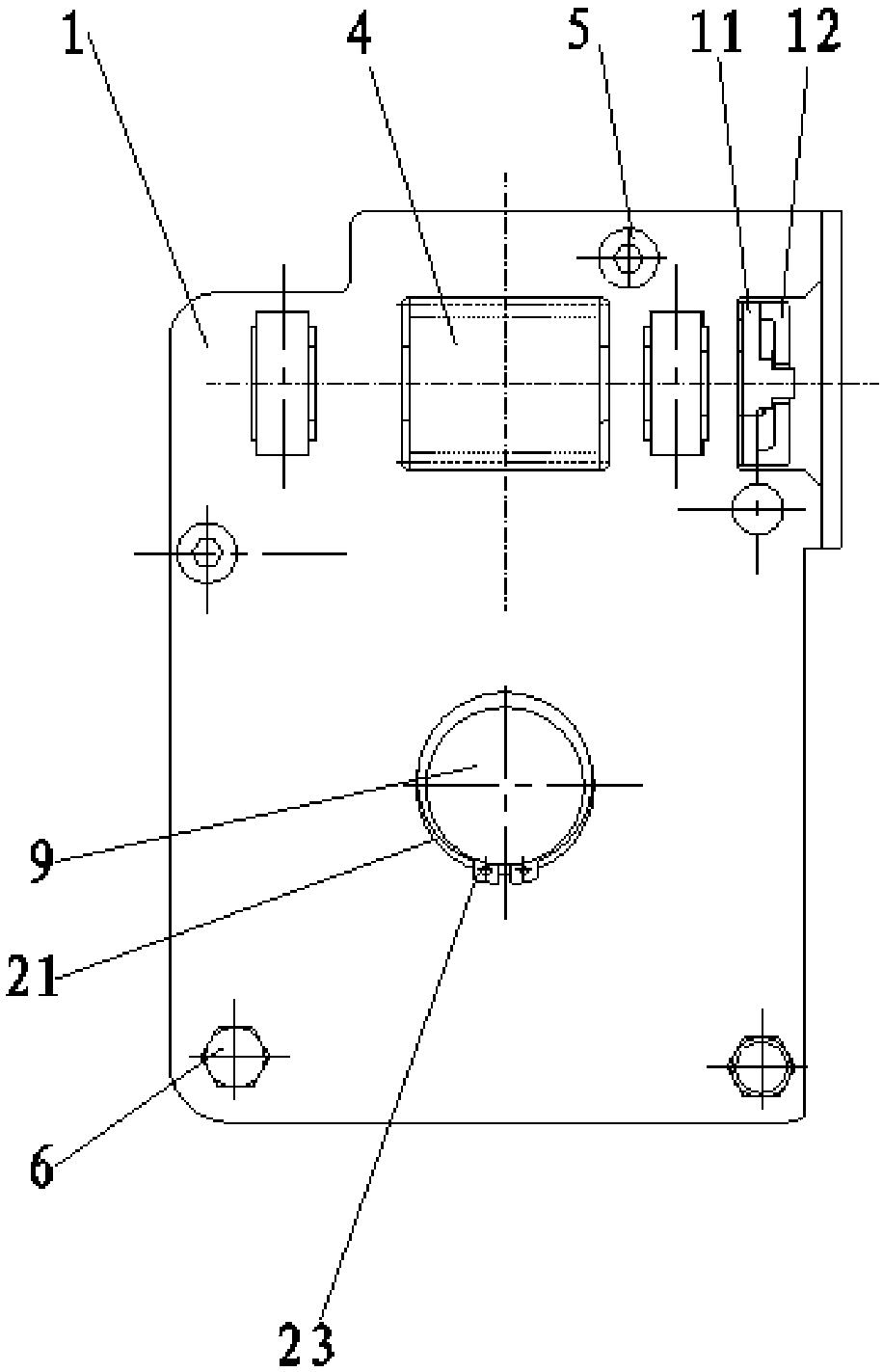
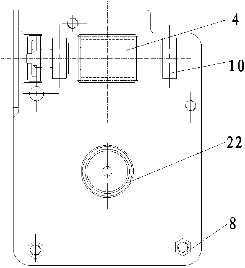
[0019] see Figure 1-4 , the present invention provides a technical solution: a worm gear reducer, including an upper cover 1, a lower cover 2, a worm wheel 3, a worm 4, an inner cam 13 and an output sleeve 15, an upper cover 1 and a lower cover 2 The screw 5 and the hexagonal bolt 6 are fixedly connected, the outer side of the hexagonal bolt 6 is provided with a spacer 7, the hexagonal bolt 6 is connected with the nut 8, the worm wheel 3 and the worm 4 are me...


PUM


Abstract

The invention discloses a worm gear reducer which comprises an upper cover plate, a lower cover plate, a worm gear, a worm, an inner cam and an output sleeve. The upper cover plate and the lower cover plate are fixedly connected through a screw and a hexagon bolt. The worm gear and the worm are located in a containing space defined by the upper cover plate and the lower cover plate. An output shaft is arranged in the center of the worm gear. The worm is fixedly arranged above the worm gear. The worm gear and the worm are meshed. The two ends of the worm are fixedly provided with bearings respectively. One end of the worm is connected with a first connector and a second connector through one bearing. The inner cam is fixedly arranged on the worm wheel. The center of the inner cam is provided with the output sleeve. The output sleeve is matched with the output shaft. The output sleeve is provided with two pawls and a cam. The pawls are symmetrically arranged on the two sides of the cam. The output shaft is sleeved with the cam. The worm gear reducer is simple in structural principle, small in size, low in cost and capable of achieving output at the larger transmission ration, and the speed reduction efficiency is improved.

Description

technical field [0001] The invention relates to the technical field of reducers, in particular to a worm gear reducer. Background technique [0002] The speed reducer plays the role of matching speed and transmitting torque between the prime mover and the working machine or the actuator. The speed reducer is a relatively precise machine. The purpose of using it is to reduce the speed and increase the torque. It is often used as a reduction transmission device between the prime mover and the working machine. It plays the role of matching the speed and transmitting torque between the prime mover and the working machine or the actuator to meet the work needs. It is also used for speeding up in some occasions. It is called a speed increaser. When selecting a reducer, it should be based on the selection conditions of the working machine, technical parameters, performance of the power machine, economy and other factors, and compare the outer dimensions, transmission efficiency, ca...

Claims


Application Information

Patent Timeline
Patent Type & Authority Patents(China)
IPC IPC(8): F16H37/14F16H57/039
CPCF16H37/14F16H57/039
Inventor 张华平唐勇
Owner CHANGSHA AIKERUI GEAR MACHINERY
Why Eureka
Try Eureka