
A multi-shell-side shell-and-tube heat exchanger

A shell-and-tube heat exchanger and multi-shell pass technology, which is applied to the types of heat exchangers, heat exchanger shells, indirect heat exchangers, etc., can solve the problems of increasing equipment use space, long retention time of refrigerant circulation, increasing Refrigerant supply chain workload and other issues to achieve the effect of reducing workload

Active Publication Date: 2018-01-30
NA SHENG CLEAN TECH SUZHOU CO LTD
View PDF8 Cites 0 Cited by
  • Summary
  • Abstract
  • Description
  • Claims
  • Application Information

AI Technical Summary

Problems solved by technology

[0005] One solution is to allow water to pass through multiple heat exchangers continuously to achieve multi-stage cooling, but this method results in increased cost and occupied space
[0006] Another solution is to increase the heat exchange area of ​​a single heat exchanger. However, this method leads to an increase in the volume of the heat exchanger, and the refrigerant stays in a shell for too long, which may easily cause a large temperature difference between the inlet and outlet of the refrigerant. It increases the use space of the equipment and increases the workload of the refrigerant supply chain

Method used


Image

  • A multi-shell-side shell-and-tube heat exchanger
  • A multi-shell-side shell-and-tube heat exchanger
  • A multi-shell-side shell-and-tube heat exchanger

Examples


Embodiment 1

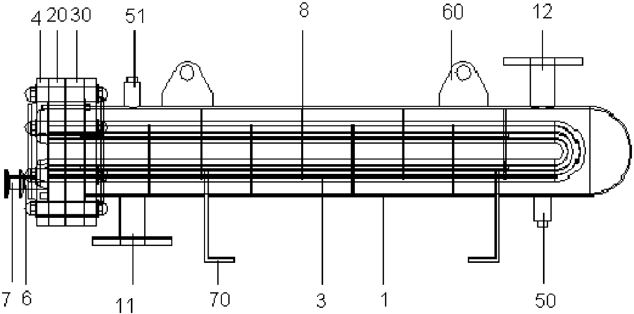
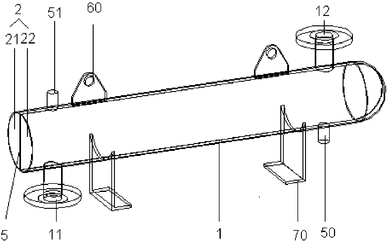
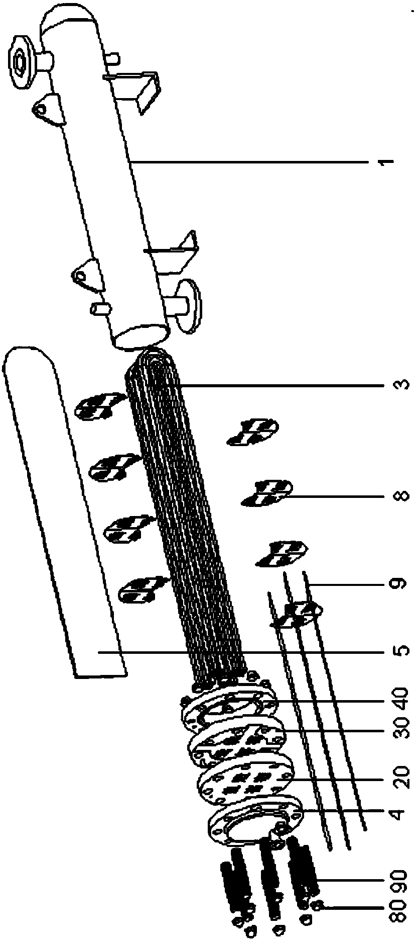
[0029] Embodiment one: if Figures 1 to 5 As shown, the present invention provides a multi-shell-side shell-and-tube heat exchanger, which belongs to the field of fluid temperature control and can be used to cool heat medium. The embodiment will be further described in detail below with reference to the accompanying drawings.

[0030] Such as Figures 1 to 3 As shown, the multi-shell-side shell-and-tube heat exchanger provided in this embodiment includes a shell side 1, and a housing cavity 2 is arranged in the shell side 1, and a heat transfer tube bundle 3 is accommodated in the housing cavity 2, and one end of the shell side 1 is provided with There is a flat cover head 4. Wherein, the housing chamber 2 of the shell side 1 is provided with an isolation plate 5, and the isolation plate 5 is fixed on the inner surface of the accommodation chamber 2 by a fixing block (not shown in the figure). There can be one, two or more isolation plates 5, and the isolation plates 5 equal...

Embodiment 2

[0045] Embodiment 2: The present invention provides a multi-shell-side shell-and-tube heat exchanger, which is basically the same in structure as the shell-and-tube heat exchanger described in Embodiment 1, except that two isolation plates are arranged in the storage cavity, and the isolation plates will The accommodation cavity is divided into a first cavity, a second cavity and a third cavity, and the heat transfer tube bundle includes a primary tube bundle located in the first cavity, a secondary tube bundle located in the second cavity, and a three-stage tube bundle located in the third cavity. The first-stage tube bundle, the first-stage tube bundle, the second-stage tube bundle, and the triode tube bundle are connected back and forth; the medium in the first-stage tube bundle passes through the refrigerant in the first cavity for primary heat exchange, and then enters the second-stage tube bundle for secondary heat exchange in the second cavity. The heat exchange will fin...


PUM


Abstract

The invention relates to a multi-shell-side shell-and-tube heat exchanger. The multi-shell-side shell-and-tube heat exchanger comprises a shell side. A containing cavity is formed in the shell side, a heat transfer tube bank is contained in the containing cavity, a dividing plate is further arranged in the containing cavity of the shell side and divides the containing cavity into a first cavity body and a second cavity body, and the first cavity body and the second cavity body are not communicated. The heat transfer tube bank comprises a first-stage tube bank body located in the first cavity body and a second-stage tube bank body located in the second cavity body, and the first-stage tube bank body and the second-stage tube bank body are connected front and back. After being subjected to first-stage heat exchange in the first cavity body with a coolant, a medium in the first-stage tube bank body enters the second-stage tube bank body and is subjected to second-stage heat exchange in the second cavity body. According to the multi-shell-side shell-and-tube heat exchanger, the shell side is evenly divided into the non-communicated cavity bodies through the dividing plate, multi-stage cooling of the heat transfer tube tank is achieved through the cavity bodies in sequence, the temperature of the medium can be suddenly decreased, and the temperature difference between a coolant inlet and a coolant outlet can be small; due to the slope design of the heat transfer tube bank, liquid is prevented from remaining in the tube bank, and the cleanliness of the heat transfer tube bank reaches the hygiene grade.

Description

technical field [0001] The invention belongs to the field of fluid temperature control, in particular to a multi-shell-side shell-and-tube heat exchanger. Background technique [0002] A heat exchanger, also known as a heat exchanger, is a device that transfers part of the heat of a hot fluid to a cold fluid. Heat exchangers are common equipment in chemical industry, petroleum, power, food and many other industrial sectors. They play an important role in production and can be used for heating medium and cooling medium. [0003] In the current biopharmaceutical field, each process basically has certain process requirements, especially for the temperature of the water used. The following takes the water cooling process as an example. For example, when cleaning equipment, it is required to reduce the injection water from 80°C to about 20°C instantaneously; when preparing biological products, it is required to reduce the water from 80°C to 2-8 ℃. Therefore, it is usually nece...

Claims


Application Information

Patent Timeline
Patent Type & Authority Patents(China)
IPC IPC(8): F28D7/06F28F9/26
CPCF28D7/06F28F9/26
Inventor 鲁新红
Owner NA SHENG CLEAN TECH SUZHOU CO LTD
Learn More