
A multi-target positioning acoustic wave emission device

A multi-target positioning and sound wave emission technology, which is applied in the re-radiation of sound waves, measuring devices, and utilization of re-radiation, can solve problems such as high working noise, inability to identify types of reflective objects, and inability to achieve positioning and measurement, and solve the problem of heat generation Effect

Active Publication Date: 2019-02-26
杭州聚声科技有限公司
View PDF8 Cites 0 Cited by
  • Summary
  • Abstract
  • Description
  • Claims
  • Application Information

AI Technical Summary

Problems solved by technology

In addition, this method can only measure the distance of the reflector, neither can it identify the type of reflector, nor can it reflect the number of reflectors.
Especially for the excavation process of tunnels such as railways and highways, the positioning of multiple targets (positioning of multiple workers at different positions) between the second lining and the tunnel face often requires a sound wave emission distance of more than 200 meters, and the tunnel face where the sound waves reach Due to the very loud working noise of pneumatic drills, excavators, loaders, and heavy-duty transport vehicles, the existing distance-measuring ultrasonic waves cannot achieve the purpose of positioning measurement due to long-distance attenuation and masking effect of strong background noise.

Method used


Image

  • A multi-target positioning acoustic wave emission device
  • A multi-target positioning acoustic wave emission device
  • A multi-target positioning acoustic wave emission device

Examples


Embodiment Construction

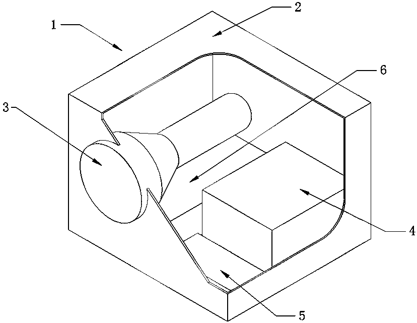
[0019] see figure 1 , the present invention 1 can be fixed with bolts or steel strips, and when used in tunnel construction, it can be fixed on the crossbeam of the second lining trolley, and the transmitting end of the transducer points to the construction face. For other applications, on the premise of ensuring that the transmitting end of the transducer points to the multi-targets that need to be positioned, the device of the present invention can be fixed on a fixed or mobile bracket and then used. The present invention can not only be used for the positioning of construction personnel between the second lining and the tunnel face in tunnel excavation projects such as railways and highways, but also can be used for determining the moving position and staying time of personnel in squares, exhibitions, parks and other occasions.

[0020] see figure 1 1. Input 220V (100V to 240V can work) AC mains power to the sound wave emission device 1 for multi-target positioning, turn o...


PUM


Abstract

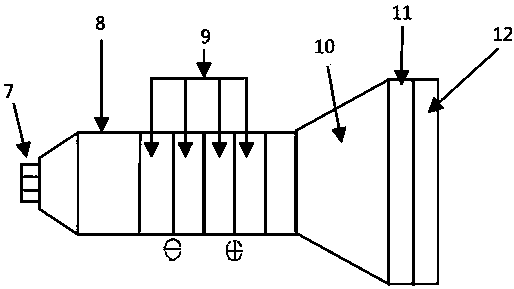
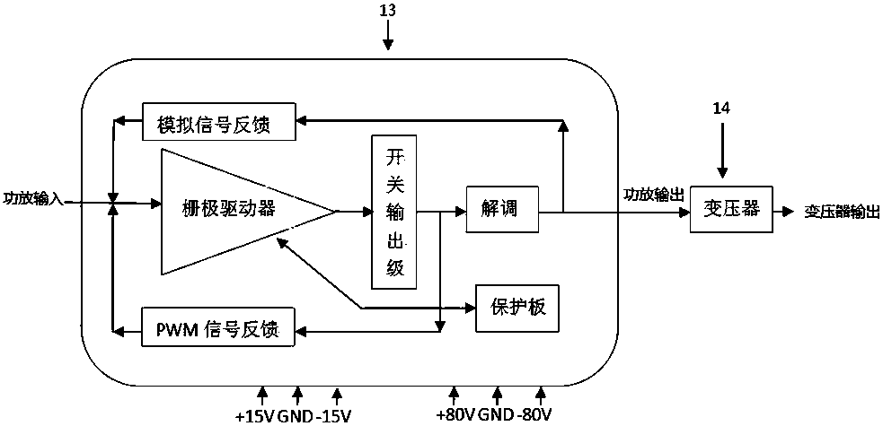
The invention belongs to the ultrasonic wave positioning technical field and relates to an acoustic wave transmitting device for multi-target positioning. The device is composed of a shell, a transducer, a switching power amplifier, a signal processor and a switching power source; 220V alternating current is inputted into the device; the switching power source supplies power for the signal processor and the switching power amplifier so as to make the signal processor and the switching power amplifier operate; the signal processor outputs intermittent simple harmonic signals; the intermittent simple harmonic signals are amplified by the switching power amplifier; the amplified signals are subjected to voltage boosting of a transformer; the intermittent simple harmonic signals processed by the transformer are supplied for the transducer so as to excite the transducer to vibrate; the transducer transmits the intermittent simple harmonic signals to target points required by the multi-target positioning, so that devices at the target points can determine distances from the target points to an ultrasonic wave transmitting point according to the speed and time of the transmission of ultrasonic waves in the air; and therefore, one-point-transmitting and multi-target simultaneous receiving positioning can be realized. The acoustic wave transmitting device of the invention can be applied to the positioning of construction personnel between a secondary lining and a tunnel face in a tunnel excavation project of a railway, a highway and the like, and can be also applied to the determination of the movement positions and stay time of peoples in places such as squares, exhibitions and parks.

Description

technical field [0001] The invention belongs to the technical field of ultrasonic positioning, and in particular relates to an acoustic wave emitting device which can be used for multi-target positioning. Background technique [0002] Generally, the method of using acoustic wave emission for distance measurement or positioning is mostly completed by using highly directional ultrasonic emission and reflection. In order to obtain a more accurate ranging effect, a highly directional ultrasonic wave is used. Since the ultrasonic wave attenuates quickly in the air, the measurement distance cannot be too far. In addition, this method can only measure the distance of the reflector, and neither can identify the type of the reflector, nor can it reflect the quantity of the reflector. Especially for the excavation process of tunnels such as railways and highways, the positioning of multiple targets (positioning of multiple workers at different positions) between the second lining and...

Claims


Application Information

Patent Timeline
Patent Type & Authority Patents(China)
IPC IPC(8): G01S7/534G01S15/06
CPCG01S7/534G01S15/06
Inventor 马建敏
Owner 杭州聚声科技有限公司
Learn More