
Light diffraction device, display substrate, touch substrate and manufacturing method of touch substrate

A display substrate and light diffraction technology, applied in the direction of diffraction grating, optics, optical components, etc., can solve the problems of difficult to meet the user's viewing angle requirements, small viewing angle, low brightness, etc., and can control the viewing angle and brightness of light to improve user experience degree of effect

Inactive Publication Date: 2016-08-24
BEIJING BOE OPTOELECTRONCIS TECH CO LTD +1
View PDF2 Cites 2 Cited by
  • Summary
  • Abstract
  • Description
  • Claims
  • Application Information

AI Technical Summary

Problems solved by technology

However, most of the existing TN (Twist Nematic, twisted nematic) mode products have a relatively small viewing angle, which is difficult to meet the user's viewing angle requirements, even the ADS (Advanced superDimension Switch, Advanced Super Dimension Switch, which has obvious advantages in wide viewing angles) field conversion technology) products, its brightness is also very low at large viewing angles

Method used


Image

  • Light diffraction device, display substrate, touch substrate and manufacturing method of touch substrate
  • Light diffraction device, display substrate, touch substrate and manufacturing method of touch substrate
  • Light diffraction device, display substrate, touch substrate and manufacturing method of touch substrate

Examples


Embodiment Construction

[0023] The following will clearly and completely describe the technical solutions in the embodiments of the present invention with reference to the accompanying drawings in the embodiments of the present invention. Obviously, the described embodiments are only part of the embodiments of the present invention, not all of them. Based on the embodiments of the present invention, all other embodiments obtained by persons of ordinary skill in the art without making creative efforts belong to the protection scope of the present invention.

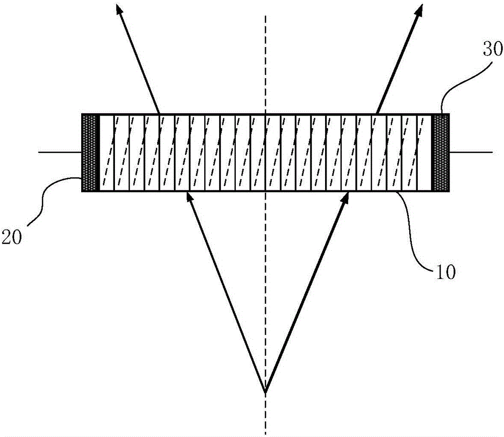
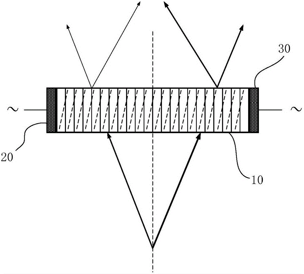
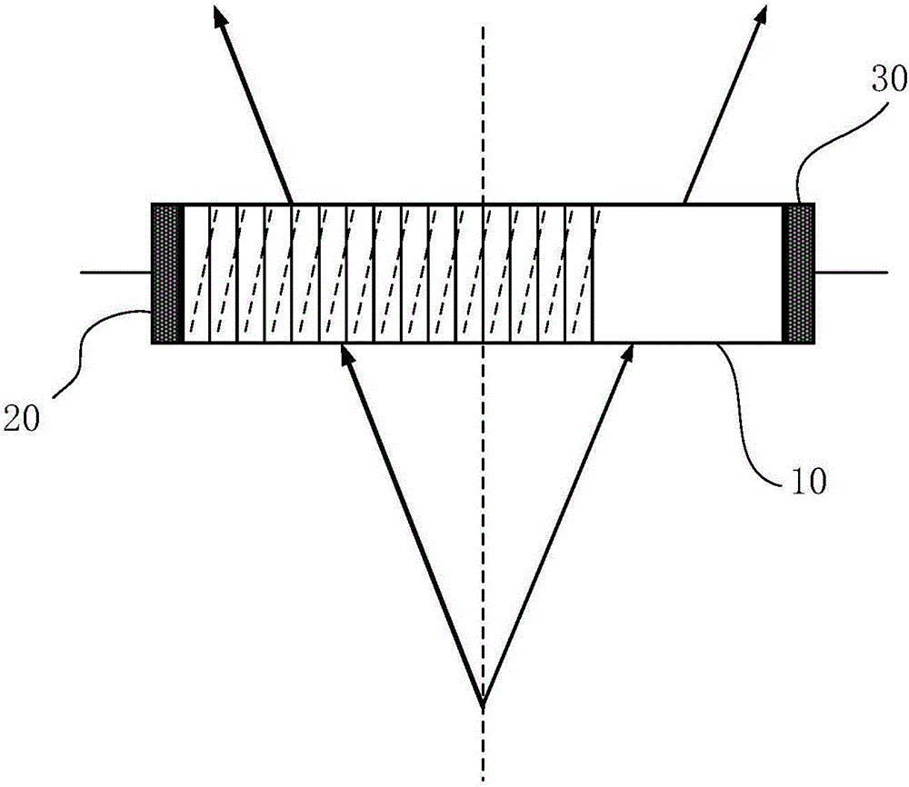
[0024] In order to achieve the purpose of the present invention, an embodiment of the present invention provides a light diffraction device, which can be arranged on the side of the light emitting surface of the display substrate, and is used to diffract the outgoing light of the display substrate, which can include: Refractive crystal block, corresponding to at least one pixel unit in the display substrate, the photorefractive crystal block is pr...


PUM


Abstract

The invention discloses a light diffraction device, a display substrate, a touch substrate and a manufacturing method of the touch substrate. The light diffraction device is used for diffracting emergent lights of the display substrate and comprises a photorefractive crystal block, an electrode structure and a control structure, wherein the photorefractive crystal block is corresponding to at least one pixel unit in the display substrate, and the photorefractive crystal block is preformed with holographic grating; the electrode structure is arranged on two opposite side surfaces of the photorefractive crystal block; and the control structure is used for inputting voltage to the electrode structure, and an electric field is formed between the two opposite side surfaces of the photorefractive crystal block, and at least part of the emergent lights passing through the display substrate is diffracted after passing through the holographic grating under the action of the electric field. By virtue of the light diffraction device disclosed by the invention, the aim that viewing angle and brightness of light rays can be controlled is achieved, so that user experience effect is improved.

Description

technical field [0001] The invention relates to the field of display technology, in particular to a light diffraction device, a display substrate, a touch substrate and a manufacturing method thereof. Background technique [0002] Under different conditions, users have different viewing angle requirements for display devices. However, most of the existing TN (Twist Nematic, twisted nematic) mode products have a relatively small viewing angle, which is difficult to meet the user's viewing angle requirements, even the ADS (Advanced superDimension Switch, Advanced Super Dimension Switch, which has obvious advantages in wide viewing angles) field conversion technology) products, its brightness is also very low at large viewing angles. Therefore, if a display device product with controllable viewing angle and brightness can be provided, it will certainly be able to satisfy users' demands for multiple viewing angles of the display device. Contents of the invention [0003] The...

Claims


Application Information

Patent Timeline
IPC IPC(8): G02B5/18G06F3/041
CPCG02B5/18G06F3/0412G06F2203/04103G02B5/1866G06F3/041G02B5/1828G02B5/1833G03H1/0248G03H2260/54G02B5/32G02B27/44G02F2201/305
Inventor 陈会顺李伟王凯旋武晓娟马力彭晓青张子敬
Owner BEIJING BOE OPTOELECTRONCIS TECH CO LTD
Learn More