
Energy-saving solar full tracking power generation components

An energy-saving and component technology, applied in the direction of feedback control, etc., can solve the problems of increasing structural complexity, power consumption, and difficult maintenance, etc., and achieve the effects of easy control and maintenance, cost saving, and reliable structure

Active Publication Date: 2019-03-08
XI'AN INST OF OPTICS & FINE MECHANICS - CHINESE ACAD OF SCI
View PDF4 Cites 0 Cited by
  • Summary
  • Abstract
  • Description
  • Claims
  • Application Information

AI Technical Summary

Problems solved by technology

[0002] Common sun tracking devices, especially two-axis tracking devices, are mostly set up separately. The reason is that if a single tracking frame moving in two directions is integrated, its structure is relatively complicated; but once it can be combined reasonably, it will obviously Reduce tracking costs and control costs; at the same time, in the existing two-axis tracking method, the use of polar axis + pitch axis will save energy; but whether it is the existing two-axis tracking device or the polar axis + pitch axis tracking In this way, each tracking device needs at least two driving motors, and then in the polar axis tracking, the rotation angle of the declination axis only changes very little every day, and only needs to be adjusted once a day. The use of motor drive not only increases the complexity of the structure, but also More power consumption, not easy to repair

Method used


Image

  • Energy-saving solar full tracking power generation components
  • Energy-saving solar full tracking power generation components
  • Energy-saving solar full tracking power generation components

Examples


Embodiment Construction

[0027] The present invention is illustrated by taking a cement powder storage and transportation tanker as an example.

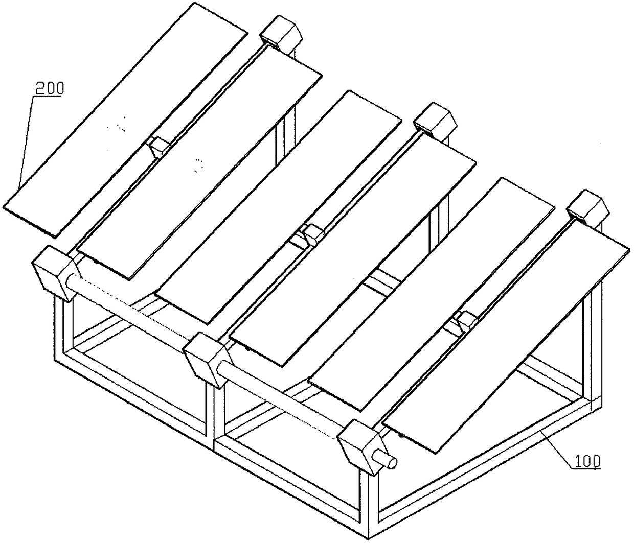
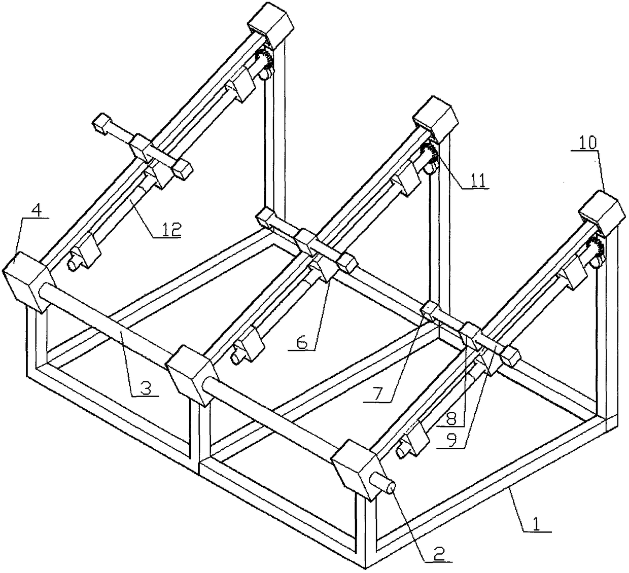
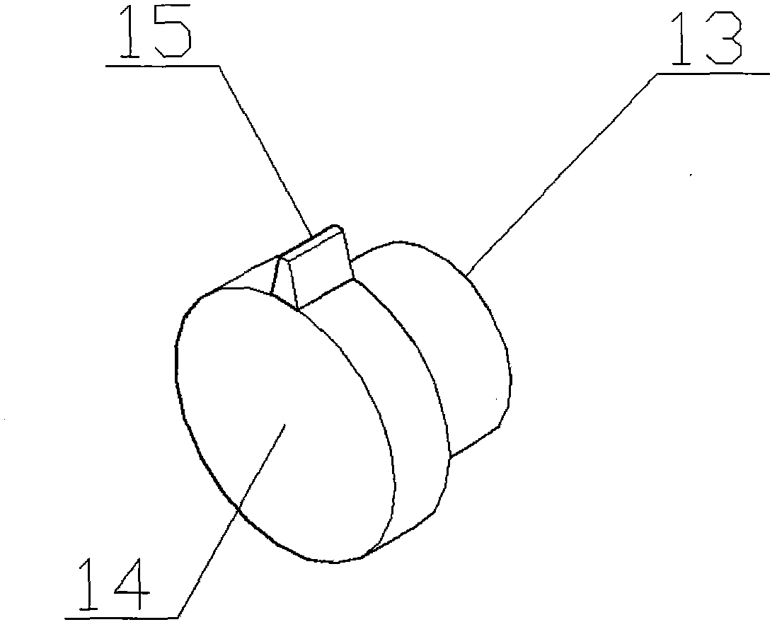
[0028] Such as figure 1 , figure 2 , image 3 with Figure 4 As shown, the energy-saving solar full-tracking power generation module of the present invention is installed in a place where the geographic latitude is β, and includes a tracking frame 100 and a photovoltaic module 200 installed on the tracking frame 100;

[0029] The tracking frame 100 includes a support 1 on which at least two sets of tracking mechanisms with the same structure are arranged in parallel;

[0030] The tracking mechanism includes a polar axis rotating shaft with a β inclination angle relative to the ground. A horizontal declination axis 9 is installed on the polar axis rotating axis. A photovoltaic mounting bracket 7 is arranged on the declination axis 9 and photovoltaic mounting bracket 7 is installed on the polar axis. Assembly 200; the declination shaft 9 is installed on the polar a...


PUM


Abstract

The invention discloses an energy-saving solar all tracking power generation component. The component comprises a tracking rack and a photovoltaic component installed on the tracking rack. The tracking rack comprises a bracket. A tracking mechanism is arranged on the bracket. The tracking mechanism comprises a pole shaft rotating shaft. A declination shaft is installed on the pole shaft rotating shaft. The declination shaft is provided with a photovoltaic installation bracket. The photovoltaic component is installed on the photovoltaic installation bracket. The declination shaft is installed on the pole shaft rotating shaft through a declination shaft transmission box. A driving lever transmission box is installed below a pole shaft. The driving lever transmission box and the declination shaft transmission box drive a declination shaft rotating shaft through a transmission component. The driving lever transmission box is rotatably installed with a driving lever parallel to the pole shaft rotating shaft. A top end of the driving lever is fixed with a gear. The gear of the driving lever rotates about the pole shaft rotating shaft which is taken as a rotation shaft. A rotation track is provided with a stirring rack. A fluted disc is installed on the stirring rack. The fluted disc is installed with a unidirectional tooth meshed with the gear of the top end of the driving lever. The pole shaft rotating shaft is driven by a driving motor.

Description

Technical field [0001] The invention relates to a photovoltaic power generation device, in particular to a solar tracking power generation device. Background technique [0002] Common sun tracking devices, especially dual-axis tracking devices, are mostly installed separately. The reason is that if a single tracking frame with two-direction motion is integrated, its structure is relatively complicated; but if it can be combined reasonably, it will obviously be Reduce tracking costs and control costs; at the same time, in the existing dual-axis tracking methods, the use of polar axis + pitch axis will have an energy-saving effect; but whether it is an existing dual-axis tracking device or a polar axis + tilt axis tracking In this way, each tracking device needs at least two driving motors. Then, in polar tracking, the rotation angle of the declination axis only changes very little every day, and only needs to be adjusted once a day. The use of motor drive not only increases the co...

Claims


Application Information

Patent Timeline
Patent Type & Authority Patents(China)
IPC IPC(8): G05D3/12
Inventor 曹捷张国琦
Owner XI'AN INST OF OPTICS & FINE MECHANICS - CHINESE ACAD OF SCI
Learn More