
Vending machine

A technology of vending machine and transmission mechanism, applied in instruments, coin-operated equipment for distributing discrete items, coin-operated equipment for distributing discrete items, etc., can solve maintenance difficulties, slow transmission speed, poor user experience, etc. problems, to achieve the effect of convenient and quick maintenance and pick-and-place currency, automatic correction of offsets, and optimization of the shipping process

Active Publication Date: 2016-08-24
百越(天津)机械有限公司
View PDF7 Cites 27 Cited by
  • Summary
  • Abstract
  • Description
  • Claims
  • Application Information

AI Technical Summary

Problems solved by technology

The existing self-service vending machines have a relatively primitive structure during the delivery process. Basically, they roll down from the upper cargo lane. discount
The reason is mainly because it is impossible to pick up the goods from the cargo lane and achieve accurate delivery
In addition, the transmission speed of the current transmission device is slow, the efficiency is low, and the user experience is extremely poor. Due to the possible deviation between various links, this also leads to the unsmooth transportation process of the existing equipment to the goods, which is also a violent shipping method. s reason
In addition, the electromechanical structure of the control cabinet of the existing vending machine is complicated, chaotic and disorderly, and maintenance is difficult
Since the current control cabinets all adopt the rear opening type, when a fault occurs, maintenance is very difficult, and the control cabinet needs to be moved to complete the maintenance operation
Some control cabinets reserve maintenance space behind, which makes the entire control cabinet occupy a very large space, and the space distribution is extremely unreasonable
At present, there are no good solutions to these problems

Method used


Image

  • Vending machine
  • Vending machine
  • Vending machine

Examples


Embodiment Construction

[0043] In order to clearly illustrate the technical features of this solution, the present invention will be described in detail below through specific implementation modes and in conjunction with the accompanying drawings.

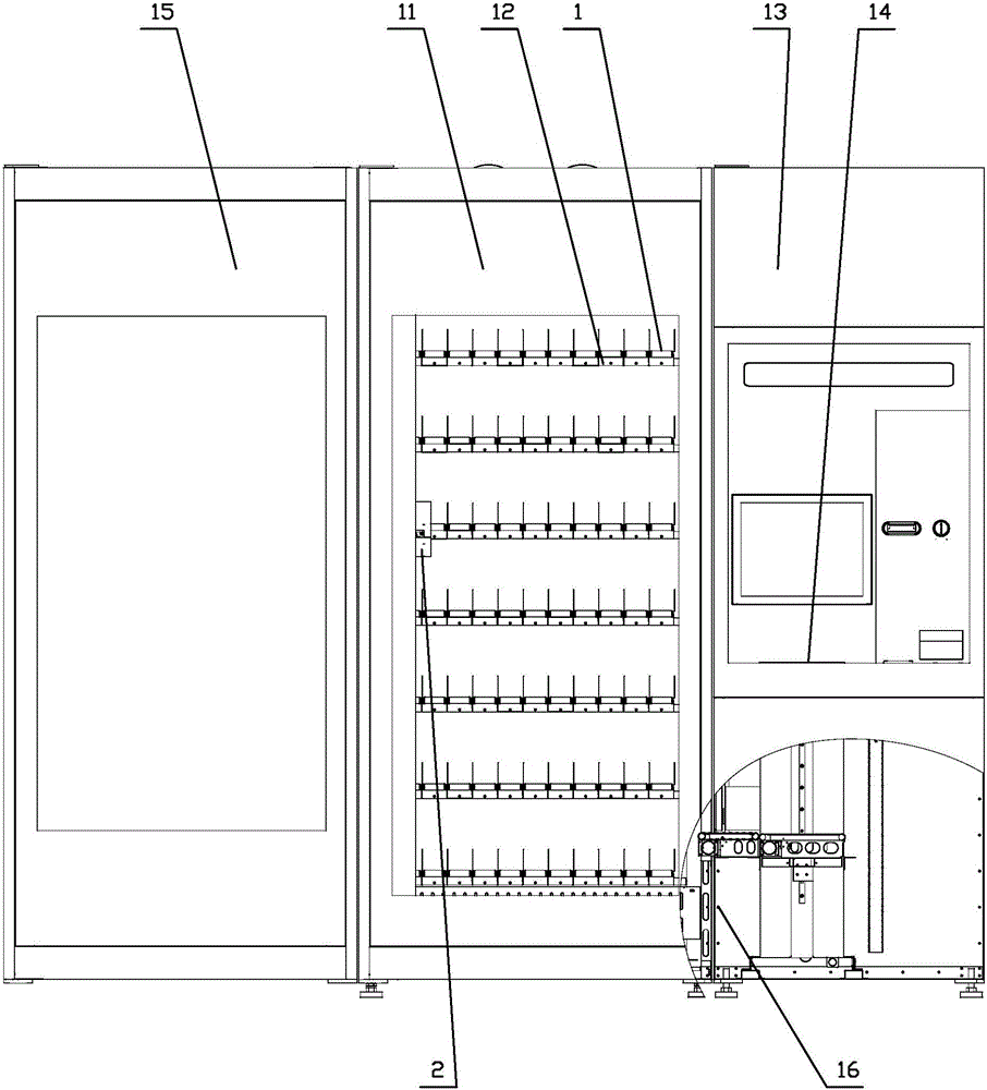
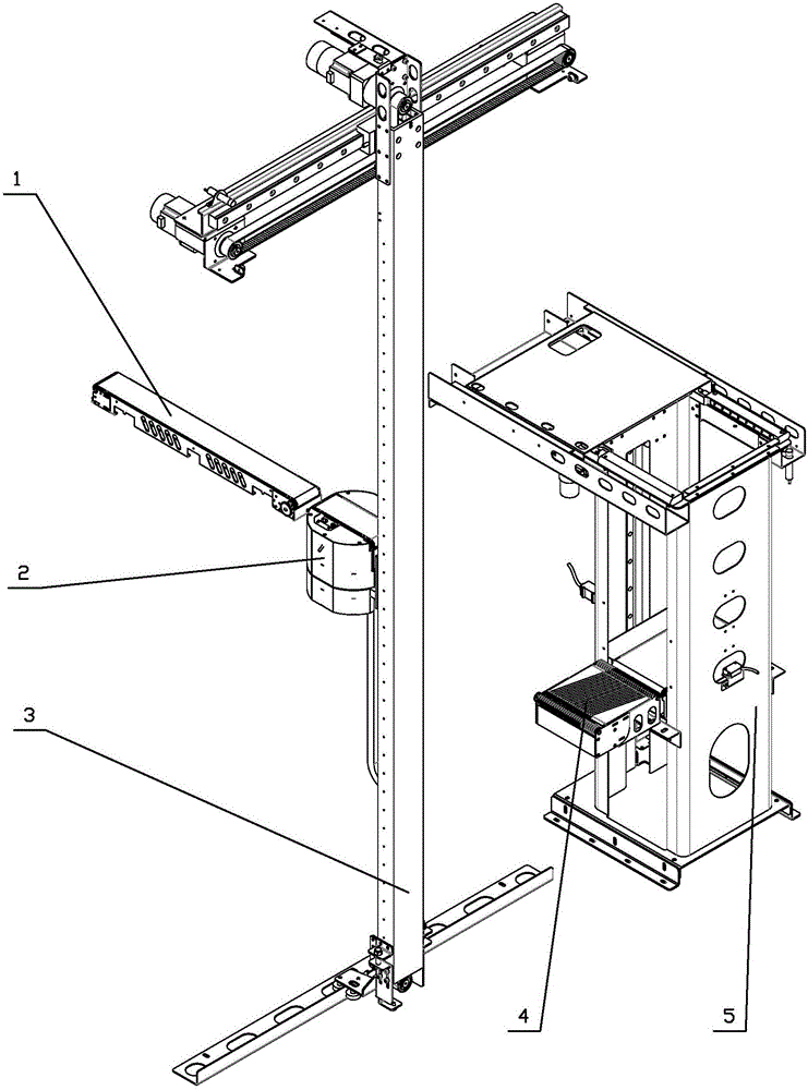
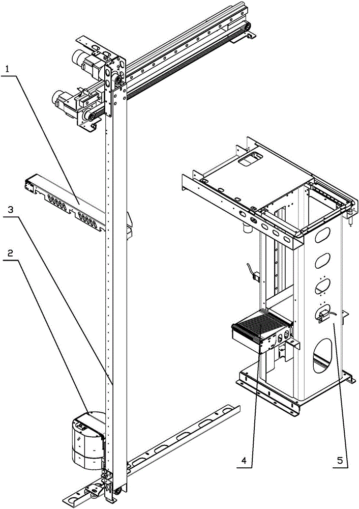
[0044] like Figure 1-26 As shown, a kind of automatic vending machine comprises container 11, in container 11 is provided with several rows of parallel distributed single-layer shelves 12 connected with container 11 shell, is provided with several cargo lanes 1 on single-layer shelf 12, in The outside of the cargo lane 1 in the container 11 is provided with a cargo conveying device that matches the cargo lane 1; a control cabinet 13 is provided on one side of the container 11, and an opening opposite to the end position of the cargo conveying device is provided on the control cabinet 13. The pick-up port 14 that is set on.

[0045] On the other side of the container 11 relative to the control cabinet 13, an advertising cabinet 15 is provided, and a lock...


PUM


Abstract

The invention relates to a vending machine which comprises a counter, wherein a plurality of rows of monolayer shelves which are distributed in parallel and connected with a counter shell are arranged in the counter; a plurality of goods channels are arranged on the monolayer shelves; goods conveying devices matched with the goods channels are arranged on the outer side of the goods channels in the counter; a control cabinet is arranged on one side of the counter; a goods exit which has an upward opening and is opposite to the tail end position of the goods conveying devices is arranged on the control cabinet. The vending machine has a reasonable structure; the maintenance of the control cabinet is simple and convenient; through the combination of the goods channels, a machine head, XY directional driving mechanisms, an eccentric filtering device and a promoting device, the goods can be quickly discharged; the offset can be automatically corrected; the goods discharging process can be optimized; the control precision is high.

Description

Technical field: [0001] The invention relates to an automatic vending machine. Background technique: [0002] At present, with the gradual development and maturity of vending machine technology, vending machines are more and more widely used and deployed more and more. They can be seen everywhere in subway stations, shopping malls, and office buildings, and have formed huge business opportunities. Correspondingly, the research on vending machines is also expanding, and the types of vending machines are also different. There are more and more products that can be vended automatically, led by beverage and food vending machines, making people more convenient in their daily lives. The existing self-service vending machines have a relatively primitive structure during the delivery process. Basically, they roll down from the upper cargo lane. discount. The reason is mainly because it is impossible to pick up the goods from the cargo lane and realize accurate delivery. In addit...

Claims


Application Information

Patent Timeline
Patent Type & Authority Applications(China)
IPC IPC(8): G07F11/58
CPCG07F11/58
Inventor 赵树希董超
Owner 百越(天津)机械有限公司
Learn More