
Cooling patch for smart home

A heat dissipation patch and smart home technology, applied in the direction of cooling/ventilation/heating transformation, electrical components, electrical equipment structural parts, etc., can solve the problems of poor heat dissipation of heating appliances, etc., to facilitate installation and disassembly, and enhance application range, the effect of reducing manufacturing costs

Inactive Publication Date: 2016-08-24
CHENGDU ZHONGFU LIXIANG TECH
View PDF0 Cites 0 Cited by
  • Summary
  • Abstract
  • Description
  • Claims
  • Application Information

AI Technical Summary

Problems solved by technology

[0003] The present invention overcomes the deficiencies of the prior art, provides a heat dissipation patch for smart homes, and solves the problem of poor heat dissipation of existing old-fashioned refrigerators or computer cases and other heating appliances

Method used


Image

  • Cooling patch for smart home
  • Cooling patch for smart home
  • Cooling patch for smart home

Examples


Embodiment 1

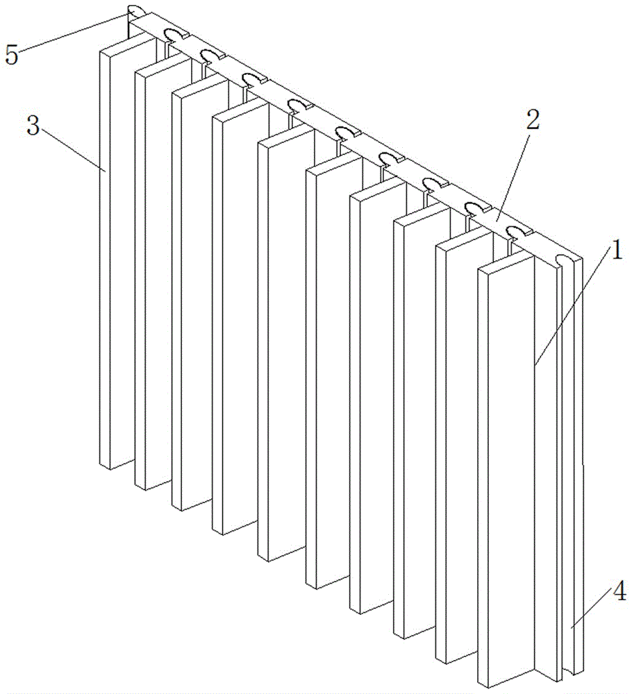
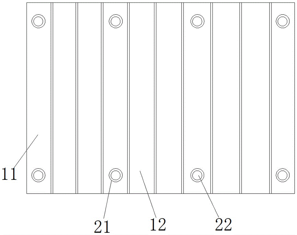
[0019] Such as figure 1 , figure 2 , image 3 , Figure 4 A heat dissipation patch for smart home is shown, which includes a plurality of single patch 1, and said single patch 1 includes a first single patch 11 and a second single patch 12, said The first monomer patch 11 and the second monomer patch 12 both include a base 2 and a heat dissipation plate 3, and the heat dissipation plate 3 is installed on the base 2; one side of the base 2 is provided with a connecting groove 4, so that The other side of the base 2 is provided with a connecting protrusion 5 , and the base 2 of the first single patch 11 is provided with a mounting groove 21 , and a magnet block 22 is disposed in the mounting groove 21 .

[0020] Sticking this embodiment on electric heating parts such as refrigerators can increase the surface area of ​​its heat dissipation, thereby increasing the efficiency of heat dissipation, and this implementation can be freely combined according to the size of the heat d...

Embodiment 2

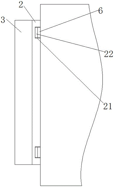
[0022] This embodiment has been further improved on the basis of embodiment 1, as figure 1 , figure 2 , image 3 , Figure 4 Shown is a kind of cooling patch for smart home, which also includes a fixed sticker 6, the sum of the thickness of the fixed sticker 6 and the thickness of the magnet block 22 is the groove depth of the installation groove 21; the fixed sticker Block 6 is an iron block.

[0023] When the shell of the electric appliance that needs to dissipate heat is not made of iron, the fixed patch 6 can be pasted on the heat dissipation part of the electric appliance in advance, and then the heat dissipation patch is attached, and the magnet block 22 and the fixed patch 6 are firmly attracted. In this way, the heat dissipation patch is fixed on the part that needs to dissipate heat.

Embodiment 3

[0025] This embodiment has been further improved on the basis of embodiment 1, as figure 1 , figure 2 , image 3 , Figure 4 As shown in the heat dissipation patch for smart home, the base 2, the heat dissipation plate 3 and the connecting convex strip 5 are metal structures. This embodiment is preferably a copper structure. Metal copper has good thermal conductivity and is relatively cheap .


PUM


Abstract

The invention discloses a cooling patch for a smart home. The cooling patch comprises single patches, a first single patch, a second single patch, a base, installation grooves, magnet blocks, cooling plates, a connection concave groove, a connection convex strip and fixed paste blocks. The cooling patch has the advantages that the cooling patch is pasted at an electrical heating part and the like of a refrigerator, the cooling surface area can be expanded, so that the cooling efficiency is improved; the cooling patch can be freely combined according to the size of the cooling area and is wide in application range; the single patch is more convenient to fabricate, and the fabrication cost is reduced; and moreover, the cooling patch is convenient to install and disassemble, can be recycled and has long service lifetime.

Description

technical field [0001] The invention relates to the field of smart home, and more specifically relates to a heat dissipation patch for smart home. Background technique [0002] Refrigerators / computers and other heating appliances tend to generate heat during use, especially for some refrigerators and computers that have been used for a long time, the heat dissipation effect will become less and less ideal, thus affecting the service life of refrigerators or computers. How to improve the heat dissipation effect of electricity is an urgent problem to be solved. Contents of the invention [0003] The invention overcomes the deficiencies of the prior art, provides a heat dissipation patch for smart homes, and solves the problem of poor heat dissipation effect of existing heating appliances such as old-fashioned refrigerators or computer cases. [0004] In order to solve the above-mentioned technical problems, the present invention adopts the following technical solutions: ...

Claims


Application Information

Patent Timeline
Patent Type & Authority Applications(China)
IPC IPC(8): H05K7/20
CPCH05K7/20418
Inventor 汪海李国
Owner CHENGDU ZHONGFU LIXIANG TECH
Learn More