Punch forming mechanism for steel plate

A stamping forming and steel plate technology, which is applied in the direction of forming tools, metal processing equipment, manufacturing tools, etc., can solve the problems of troublesome installation and disassembly, many parts, large volume, etc., and achieve the effect of convenient installation and disassembly, small volume and low energy consumption

Active Publication Date: 2016-08-31
杭州英华工艺品有限公司
View PDF5 Cites 19 Cited by
  • Summary
  • Abstract
  • Description
  • Claims
  • Application Information

AI Technical Summary

Problems solved by technology

[0002] When the existing thin and small-area steel plates are stamped and formed, the mold forming equipment used is generally large in size and has many parts, which makes the energy consumption of stamping production large and wasteful. For fixing, it is troublesome to install and disassemble

Method used


Image

  • Punch forming mechanism for steel plate
  • Punch forming mechanism for steel plate

Examples


Embodiment

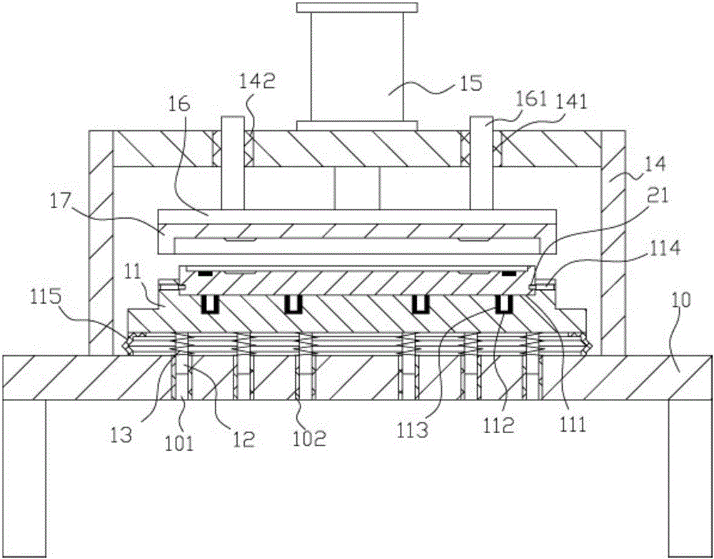
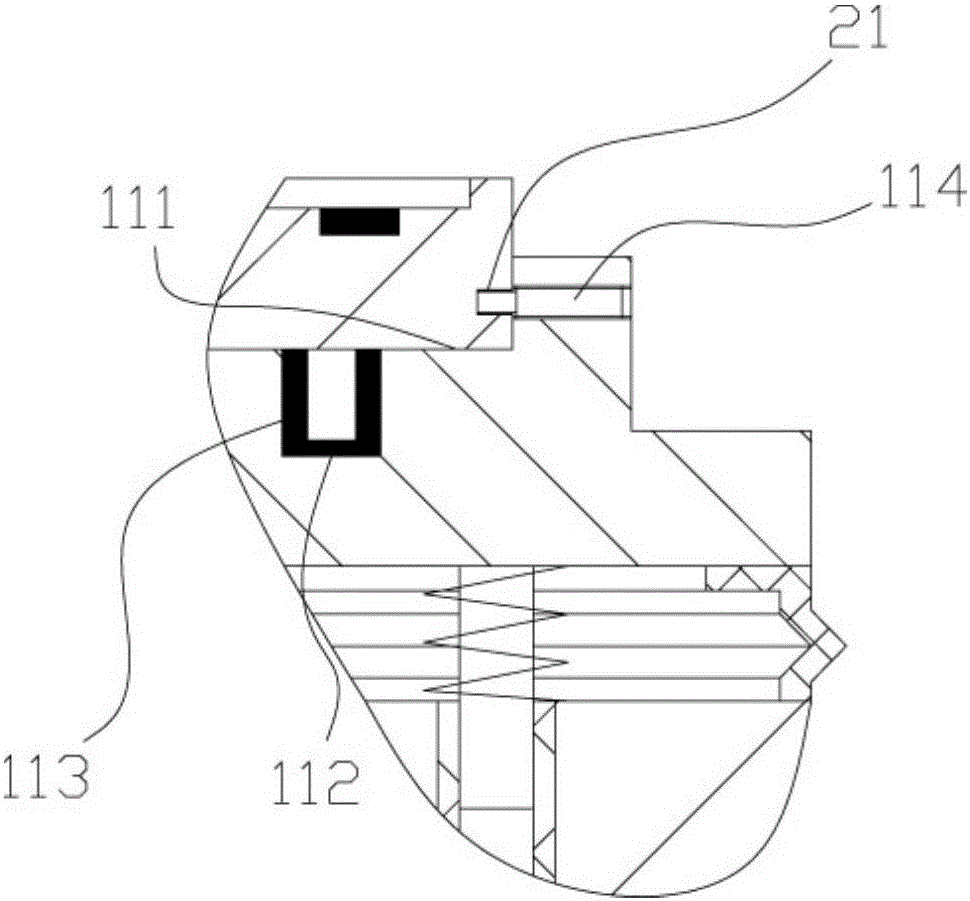
[0015] Example: see Figure 1 to Figure 2 As shown, a steel plate stamping and forming mechanism includes a frame 10, a lower mold connection block 11 is provided above the top plate of the frame 10, and a plurality of vertical inserting rods 12 are provided on the bottom surface of the lower mold connection block 11, vertically A buffer spring 13 is inserted in the insertion rod 12, and the lower end of the vertical insertion rod 12 is inserted in the jack 101 provided on the top plate of the frame 10. The upper end of the buffer spring 13 is fixed on the bottom surface of the lower mold connecting block 11, and the buffer spring The lower end of 13 is fixed on the top surface of the top plate of frame 10, and the middle part of the top surface of lower mold connection block 11 has lower mold fixing groove 111, and the bottom surface of lower mold fixing groove 111 has a plurality of positioning jacks 112, and the positioning jacks A strong magnet sleeve 113 is inserted into ...


PUM


Abstract

The invention discloses a punch forming mechanism for a steel plate. The punch forming mechanism comprises a frame. A lower die connecting block is arranged on a top plate of the frame. A plurality of vertical inserting rods are arranged on the bottom surface of the lower die connecting block. Buffer springs are inserted in and sleeved by the vertical inserting rods. The lower ends of the vertical inserting rods are inserted in and sleeved by insert holes in the top plate of the frame. The upper ends of the buffer springs are fixed on the bottom surface of the lower die connecting block. The lower ends of the buffer springs are fixed on the top surface of the top plate of the frame. A lower die fixing groove is formed in the middle of the top surface of the lower die connecting block. A plurality of positioning insert holes are formed in the bottom surface of the lower die fixing groove. Strong magnet sleeves are inserted in and sleeved by the positioning insert holes. The outside walls of the strong magnet sleeves are fixed on the inside walls of the positioning insert holes. A lower die is inserted in and sleeved by the lower die fixing groove. A plurality of inserting rods are arranged on the bottom surface of the lower die, are sleeved in and sleeved by the strong magnet sleeves, and are adsorbed in the strong magnet sleeves. The punch forming mechanism is simple in structure, small in size, and low in energy consumption, and besides, the cost is reduced, the lower die is convenient to mount and dismount, and the manufacturing effect is improved greatly.

Description

Technical field: [0001] The invention relates to the technical field of metal parts processing equipment, and more specifically relates to a steel plate stamping and forming mechanism. Background technique: [0002] When the existing thin and small-area steel plates are stamped and formed, the mold forming equipment used is generally large in size and has many parts, which makes the energy consumption of stamping production large and wasteful. For fixing, it is troublesome to install and disassemble. Invention content: [0003] The object of the present invention is to provide a steel plate stamping forming mechanism aimed at the deficiencies of the prior art, which has the advantages of simple structure, small volume, low energy consumption and cost saving. At the same time, the lower die is easy to install and disassemble, which greatly improves the production effect. [0004] Technical solutions of the present invention are as follows: [0005] A steel plate stamping ...

Claims


Application Information

Patent Timeline
Patent Type & Authority Applications(China)
IPC IPC(8): B21D22/06B21D37/10B21D37/12
CPCB21D22/06B21D37/10B21D37/12
Inventor 付淑珍
Owner 杭州英华工艺品有限公司
Why Eureka
Try Eureka