Large thin plate laser cutting clamp and machining method thereof

A technology of laser cutting and thin plate, which is applied in metal processing, laser welding equipment, metal processing equipment, etc., can solve the problems of variable shape and difficult processing, and achieve the effect of reducing manufacturing cost, solving variable shape, and improving processing efficiency

Active Publication Date: 2016-08-31
SHENYANG AIRCRAFT CORP
View PDF10 Cites 10 Cited by
  • Summary
  • Abstract
  • Description
  • Claims
  • Application Information

AI Technical Summary

Problems solved by technology

The jig processing method can effectively solve the problems of thin-plate laser cutting jigs such as variable shape and high processing difficulty, ensure the manufacturing accuracy of laser cutting jigs, thereby meet the precision requirements of parts, and improve the processing and production efficiency of laser cutting jigs and aircraft parts

Method used


Image

  • Large thin plate laser cutting clamp and machining method thereof
  • Large thin plate laser cutting clamp and machining method thereof
  • Large thin plate laser cutting clamp and machining method thereof

Examples


Embodiment Construction

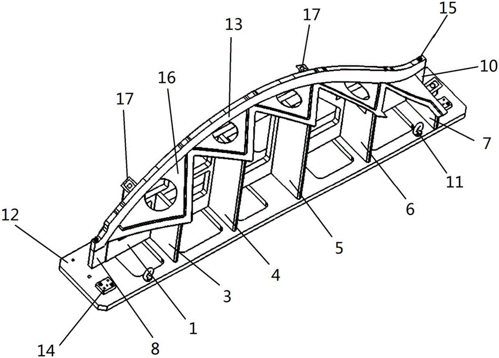
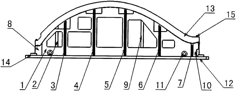
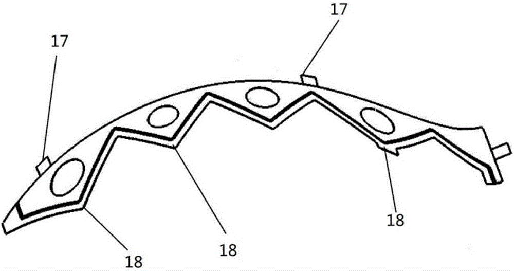
[0022] like Figure 1-2 A large thin plate laser cutting fixture is shown, which is used for clamping such as image 3 Shown aircraft skin part 16 has base plate 12 (thickness is 25mm), is provided with support frame 1 (thickness is 20mm) on base plate 12, and this support frame 1 is perpendicular to base plate 12, and the length of this support frame 1 and cover The lengths of the leather parts 16 are matched. The top surface of the support frame 1 is a curved surface I, and the curvature of the curved surface I matches the curvature of the skin part 16 .

[0023] On the bottom plate 12, there are five brackets I (thickness: 20mm) on one side of the support frame 1, which are respectively the first bracket I3, the second bracket I4, the third bracket I5, and the fourth bracket I6, and fifth bay I7. And the surface of the skin part 16 is supported by these five brackets I with different heights. The number of brackets I depends on the length of the skin part 16 and is adjus...


PUM

PropertyMeasurementUnit
thicknessaaaaaaaaaa
thicknessaaaaaaaaaa

Abstract

The invention discloses a large thin plate laser cutting clamp and a machining method thereof. The clamp is simple in structure and provided with a base plate; a support frame is arranged on and perpendicular to the base plate; the length of the support frame is matched with the length of a skin part; the top face of the support frame is a curved face I, and the curved face I is matched with the skin part in curvature; a plurality of brackets I of variable heights are arranged on one side of the support frame and on the base plate and are used for supporting the surface of the skin part; the brackets I are installed perpendicular to the base plate and the support frame; the height of each bracket I is matched with the height of the portion, corresponding to the bracket I in installation location, of the support frame; a plurality of brackets II are arranged on the other side of the support frame and on the base plate; and the brackets II are perpendicular to the base plate and the support frame correspondingly and used for supporting and fixing lugs on the skin part. According to the machining method, the problems that thin plate type laser cutting clamps are prone to deformation, high in machining difficulty and the like can be effectively solved.

Description

technical field [0001] The invention relates to the field of processing and manufacturing aircraft parts fixtures, in particular to a large thin plate laser cutting fixture and a processing method thereof. Background technique [0002] In the field of aircraft manufacturing, the precision requirements for parts are getting higher and higher, so the precision requirements for fixtures used to process parts are also higher. However, most of the fixtures used to process aircraft parts have complex structures, especially large thin plates are easy to deform The laser cutting fixture itself has the characteristics of large volume, and for the economy and practical operability of the tooling, most of the laser cutting fixtures are designed as a combined welding structure of multiple thin plate brackets. Such a structure is very easy to deform. It is difficult to guarantee the precision requirements of tooling in the production process. Contents of the invention [0003] Aiming ...

Claims


Application Information

Patent Timeline
Patent Type & Authority Applications(China)
IPC IPC(8): B23K26/70B23K26/38B23P15/00
CPCB23K26/38B23K26/702B23K2101/18B23P15/00
Inventor 刘欢王宝龙李锋
Owner SHENYANG AIRCRAFT CORP
Why Eureka
Try Eureka